65R5905752 /16 DP2K C
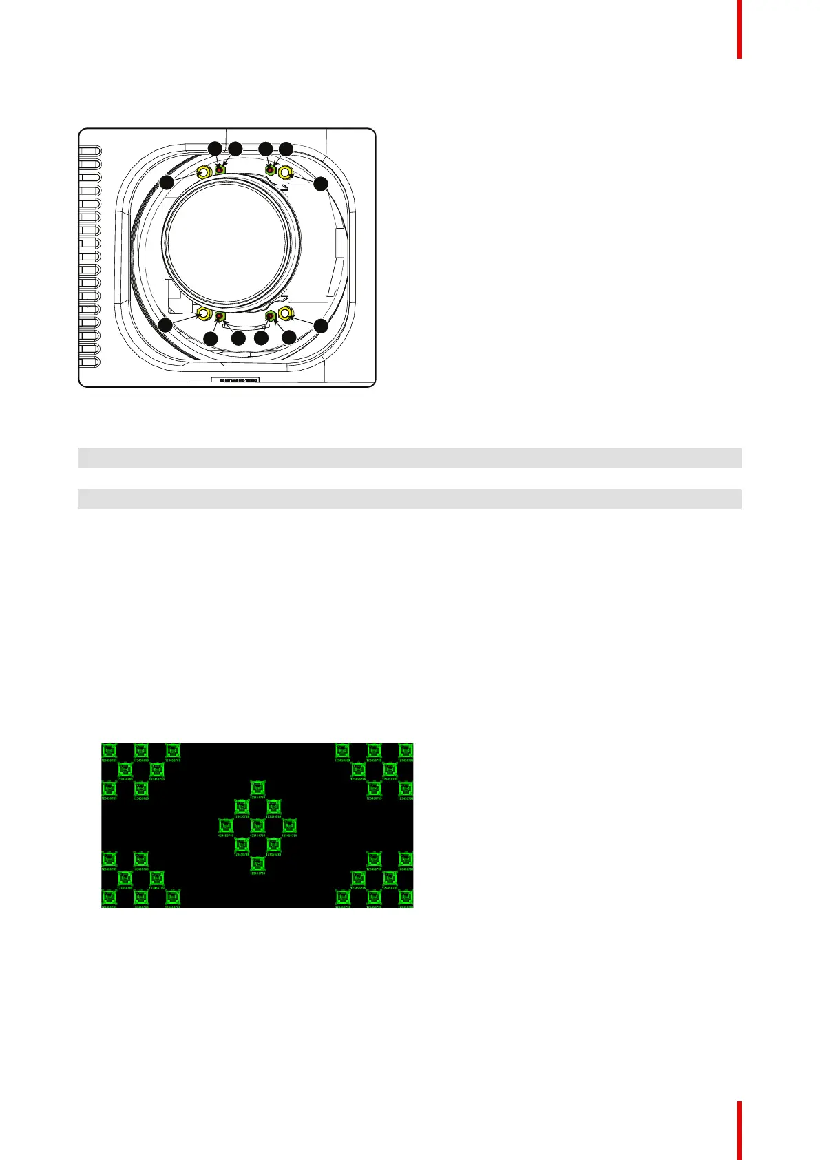
Scheimpflug adjustment points
Image 5–18 Scheimpflug adjustments
Indication on
drawing
Function
4 Locking nut
1, 2 and 3 Scheimpflug adjustment nuts
A, B, C and D Set screws
a, b, c and d lock nuts
1, 2 and 3 are adjustment points.
4 is a locking point and NOT used during Scheimpflug adjustment.
Required tools
• Allen key 3 mm
• Nut driver 13 mm
• Nut driver 10 mm
How to adjust
1. Project a green focus pattern.
Image 5–19
2. Loosen the lock nuts (a, b, c and d). See Image 5–18.
3. Loosen the 4 set screws (A, B, C and D) by 1 cm. See Image 5–18.
4. Fully loosen lock nut 4. See Image 5–18.
5. Optimize the focus of the projected image as follows:
1. Place the zoom lens in TELE position (smallest projected image) and adjust the focus using the lens
focus barrel or motorized focus control.
Lenses & lens holder
 Loading...


