31
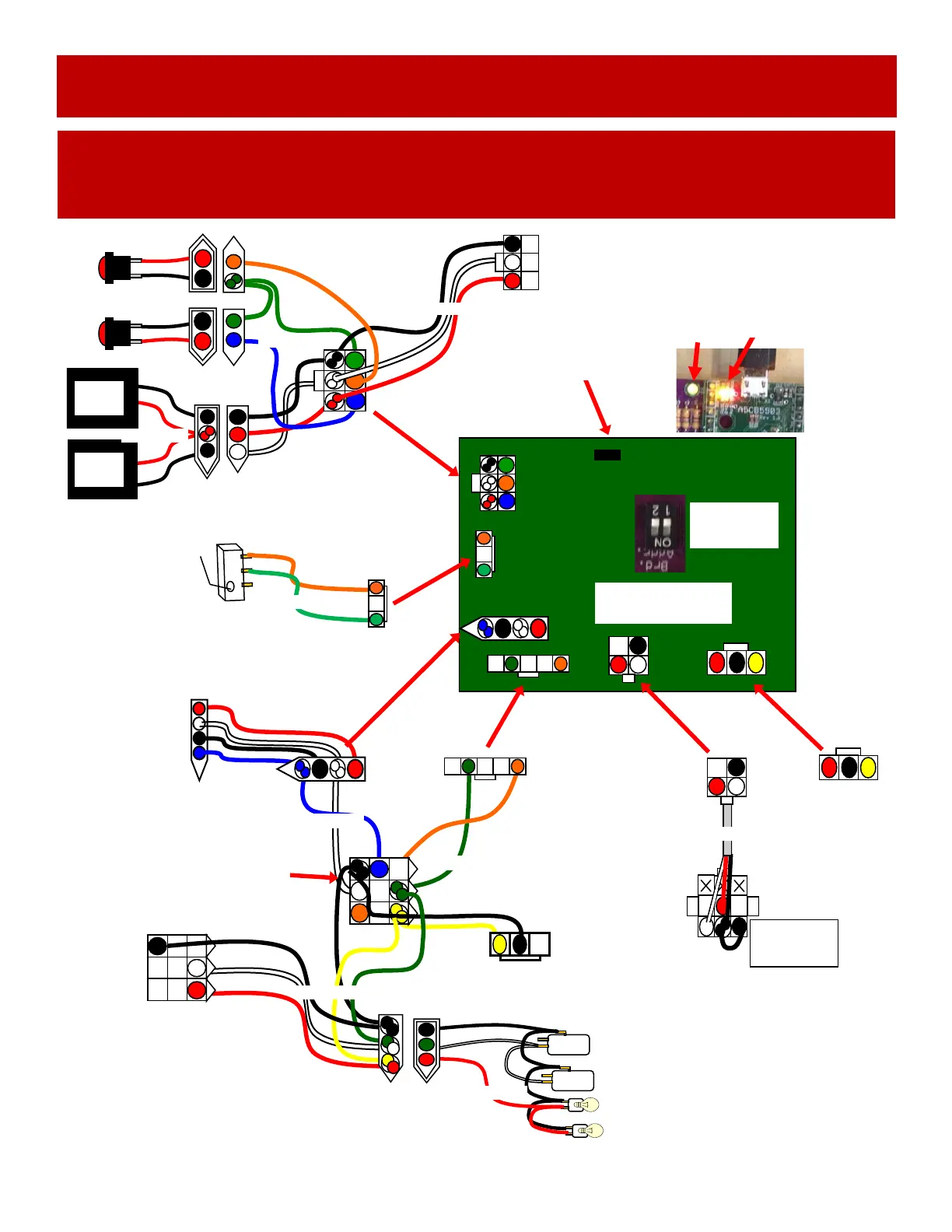
LEFT SIDE (RED) : TICKET DISPENSER, MENU
BUTTONS, METERS, DBA AND COIN MECH
WIRING DIAGRAM
Low Ticket Switch
Wired Normally Open
AASW200
1/4” Spacer A5SENY020
AACE15014
Coin Switches and Lights
To Ticket
Dispenser
Part # A5TD1
12 Volt Power
Enable Signal
Com Ground
Notch Signal
AACB9604
I/O Aux Board
Left Side
Board Address
Both Dips OFF
To 12 Volt DC
Bill Acceptor
A5AC9101
AACE15002
A5CBL5900
USB communication
to motherboard
Red and Yellow
Communication
LEDs
Green
Power
LED
AACE15038
Power in from
Power Dist Bd
From Right Side
I/O Aux Board
UCL Connector
Card Swipe system
cable would be
plugged into this
connector.
A5CBL4A-DOORA
AACE15014
AACE15014
12 Volt DC
Power from
Power Dist.
Board
Optional Coin Input Cable
located near ticket dispenser.
Card Swipe system cable
could be plugged into this
connector.
AACE15014
AACE15014
Menu
Select
AAPB2700
Menu
Button
AAPB2700
AACE15010
Game
Counter
Ticket
Counter
AACO1020
AACE15010
 Loading...