Unit Installation
5.6.2 Vertical (VT) Units
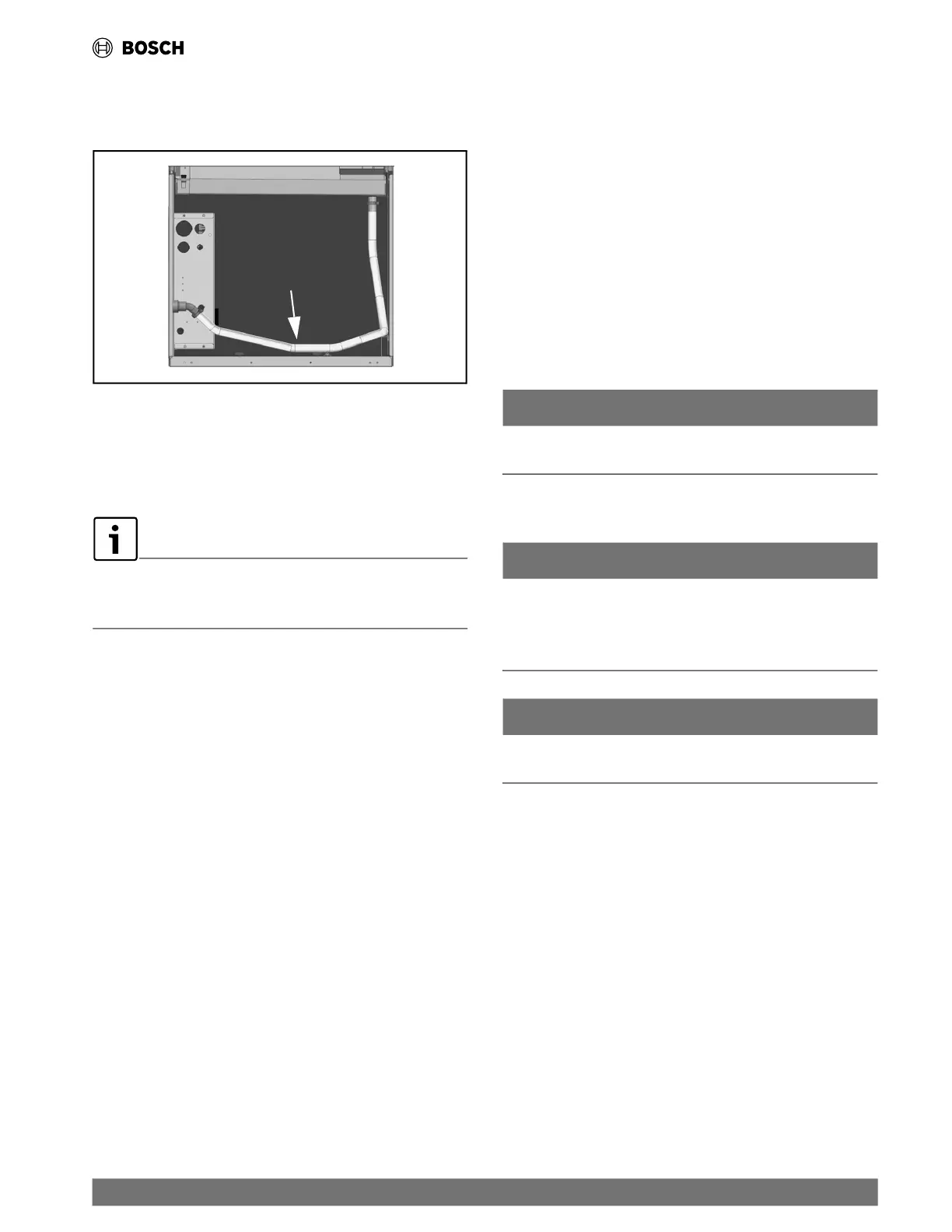
Vertical configuration units are internally trapped from the
factory. A se
cond trap must NOT be included. (See Fig. 12.)
Fig. 12 Vertical Units are Internally Trapped
Vertically-configured
units are internally
trapped from the
factory.
5.7 Duct System
All CL Series models are provided with a supply air outlet collar
and return air duct flange to facilitate duct connections.
Supply air duct and return air duct flanges are shipped unfolded with
the unit. They need to be folded.
See “Return and Supply Air Duct
Flanges Preparation” on page #13 for details.
Refer to unit Dimensional Drawings for physical dimensions of
the collar and flange. (See page #88.)
A flexible duct connector is recommended for supply and return
air duct co
nnections on metal duct systems. In order to avoid
heat loss or gain and prevent condensate forming during the
colling operation insulate all metal ducting with a minimum of 1"
duct insulation. Application of the unit to uninsulated duct work
is not recommended as the unit’s performance will be adversely
affected.
The factory filter should be left in place on a free return system.
For new or replacement market installations, please refer to
c
urrent AS
HRAE procedures for duct sizing to ensure proper
unit's operation and air distribution. If the duct system is too
small, larger duct work should be installed. Check for any leaks in
the existing duct work and repair as needed.
The duct system and all diffusers must be sized to handle the
designed
air flow quietly. To maximize sound attenuation of the
unit’s blower, insulate the supply and return air plenums. There
should be no direct straight air path through the return air grille
into the heat pump. The return air inlet to the heat pump must
have at least one 90 degree turn away from the space return air
grill. If air noise or excessive air flow are a problem, the blower
speed can be changed to a lower speed to reduce air flow.
5.8 Piping
Supply and return piping must be as large as the unit connections
on the heat pump (larger on long runs).
In order to avoid possible vibration, use flexible hose between
the unit and
the rigid system.
NOTICE
Never use flexible hoses of a smaller inside diameter than that
of the water connections on the unit.
Units are equipped with female pipe thread fittings for water
connections.
NOTICE
Piping systems that contains steel pipes or fittings may be
subject to galvanic corrosion. Dielectric fittings should be
used to isolate the steel parts of the system to avoid galvanic
corrosion.
NOTICE
DO NOT overtighten the connections to avoid damage to
threads.
Install ball valves in the supply and return lines for unit isolation
and unit water flow balancing and service.
CL units are supplied with a copper or optional cupro-nickel
condense
r. A cupro-nickel heat exchanger is recommended for
the following:
• Conditions anticipating moderate scale formation
• Brackish water
• Ground Loop application
• Ground water application
(Refer to the Water Qual
ity Table on page #28.) Water quality
must meet the standards stated in the table.
|
17
CL Series Heat Pumps — 8733838716 (2024/05)
 Loading...