Specific Application Considerations
6 Specific Application Considerations
6.1 Well Water Systems
(Refer to Fig. 15)
Refer to the Water Qualify Table on page #28 to ensure the
water quality is suitably for use with water source equipment.
In conditions of brackish water or where moderate scale
formation i
s anticipated, a cupro-nickel heat exchanger is
required. In well water applications, water pressure must always
be maintained in the heat exchanger to avoid insufficient water
flow. This can be accomplished with a control valve or a
bladder-type expansion tank. When using a single water well to
supply both d
omestic water and the heat pump care must be
taken to ensure that the well can provide sufficient flow for both.
In well water applications a slow-closing solenoid valve must be
used to prevent water hammer.
Connect the solenoid valves across Y1 and C1 on the interface
board for a
ll. Make sure that the VA draw of the valve does not
exceed the contact rating of the thermostat.
6.2 Open Well Water Systems
When a water well is used exclusively for supplying water to the
heat pump, operate the pump only when the Heat Pump
operates. A 24 volt, double-pole single-throw (DP/ST) contactor
can be used to operate the well pump with the heat pump. When
two or more units are supplied from one well, the pump can be
wired to operate independently from either unit. Two 24-volt
double-pole single-trow relays wired in parallel are required. In
either case, a larger sized VA transformer may be required.
The discharge water from the heat pump is not contaminated in
any manner
and can be disposed of in various ways depending on
local codes (i.e., discharge well, dry well, storm sewer, drain
field, stream, pond, etc.)
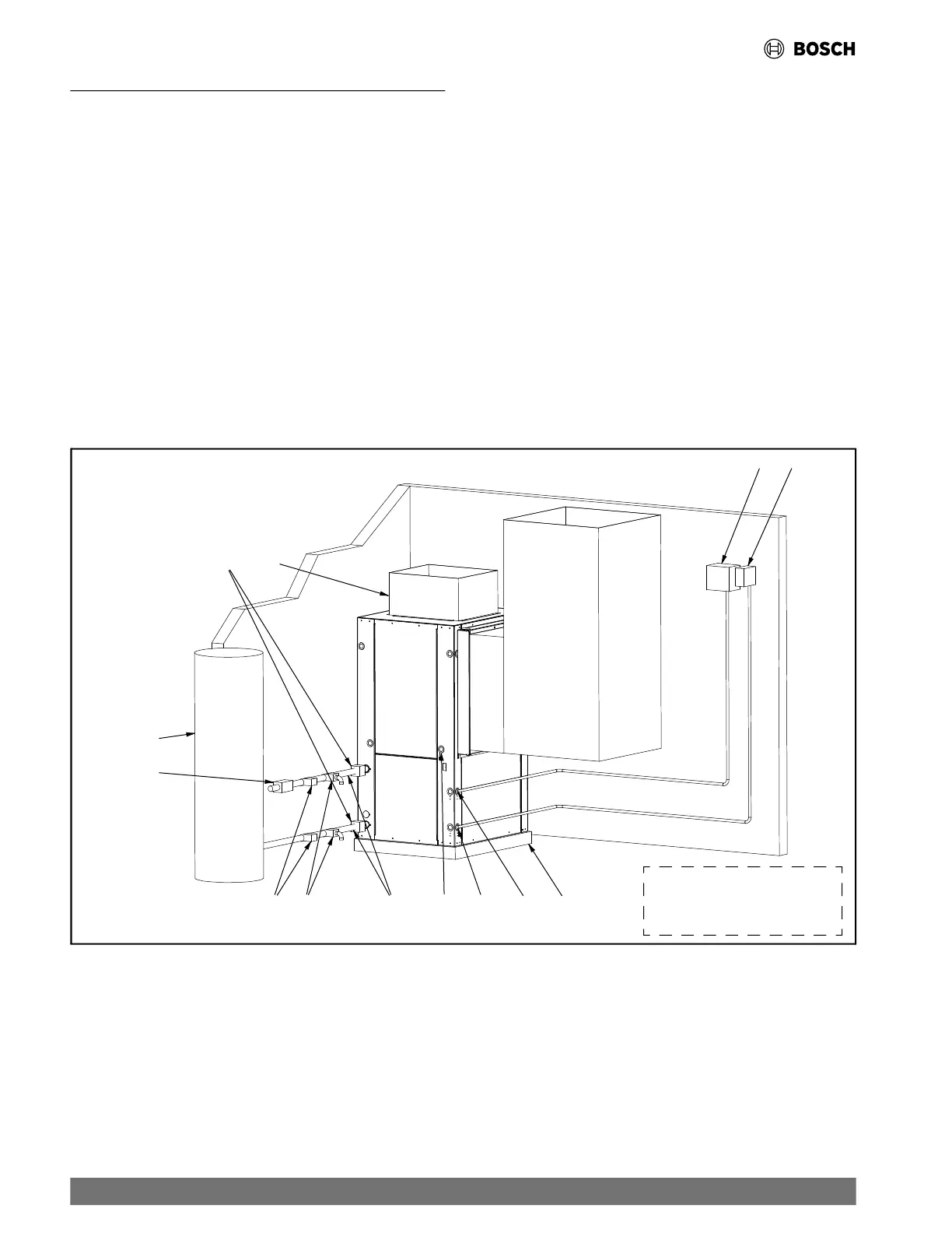
Fig. 15 Typical Well Water Setup
For Reference Only.
A typical setup is shown for
illustration purposes only.
[1] Flex Duct Connection
[2] Low-Voltage Control Connection
[3] Vibration Pad
[4] Ball Valves
[5] Solenoid Valve Slow Closing
[6] Condensate Drain Connection
[7] Drain Valves
[8] Hose Kits (optional)
[9] Pressure Tank (optional)
[10] P/T Ports (optional)
[11] Line Voltage Connection
[12] Control Panel/Thermostat
[13] Unit Line Voltage Disconnect
24 |
CL Series Heat Pumps — 8733838716 (2024/05)
 Loading...