Servicing and Repair Information
17.13 Service Access
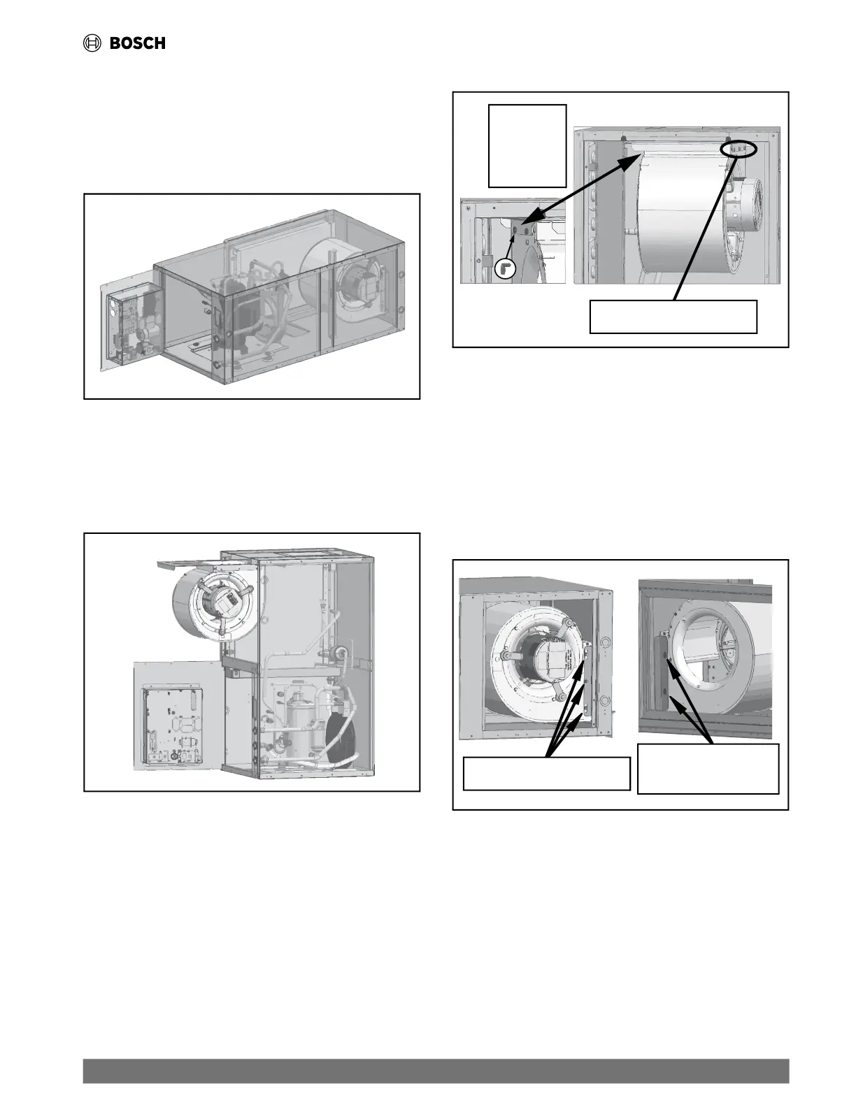
17.13.1 Swing-Out Electrical Box
The Electrical Box is designed to swing out of the way, enhancing
the unit's
accessibility and serviceability. (See Fig. 25 and Fig.
26.) For additional details, refer to section 5.9.1 on page #19.
Fig. 25 Swing-Out Electrical Box on a Horizontal Unit
17.13.2 Blower Assembly Access for Vertical Units
For vertically-configured units, the Blower Assembly is designed
to slide
out to facilitate access and servicing of the blower/motor
assembly. (See Fig. 26.)
Fig. 26 Electrical Box and Blower Assembly Access
If removal of the blower assembly is required (e.g., when
installation constraints prevent the use of the slide-out feature),
follow these steps:
Remove the three screws positioned above the motor.
Drop down and slide off the welded pins situated on the
opposite side from the motor.
(See Fig. 27.)
Fig. 27 Screws and Welded Pins Locations for Vertical Units
Weld Pins
are located
on the side
opposite
the motor.
Three screws are located
above the motor.
17.13.3 Blower Assembly Access for Horizontal Units
For horizontally-configured units, follow the steps below to
remove the B
lower Assembly:
Remove the three screws located on the motor side of the
blower assembly.
Twist and pull the blower back from welded pins located on
opposite side to the motor, near the evaporator.
(See Fig. 28.)
Fig. 28 Screws and Welded Pins Locations for Horizontal Units
Three screws are located
on the motor side.
The weld pins are
located on the side
opposite the motor.
| 53
CL Series Heat Pumps — 8733838716 (2024/05)
 Loading...