Unit Installation
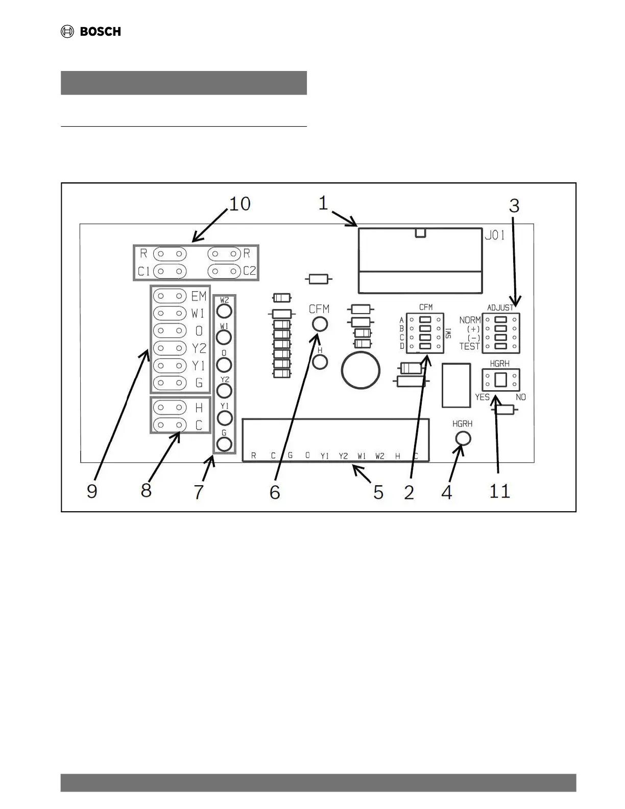
5.11 ECM Interface Board
NOTICE
ECM Interface Boards are used only with the Constant Airflow
motor option.
Thermostat wiring is connected to the 10-pin screw-type
terminal block on the lower-center portion of the ECM Interface
Board. In addition to providing a connecting point for thermostat
wiring, the interface board also translates thermostat inputs into
control commands for the Electronic Commutated Motor (ECM)
DC fan motor and displays an LED indication of operating status.
The thermostat connections and their functions are as shown in
Fig. 14.
Fig. 14 ECM Interface Board
[1] Motor Harness Plug
[2] Blower CFM Adjustment
[3] Motor Settings
[4] Dehumidification Indication
[5] Thermostat Contact Inputs
[6] CFM Count Indicator
[7] Thermostat Input Status Indication
[8] Reheat Digital Outputs
[9] Thermostat Outputs
[10] 24 VAC
[11] Hot Gas Re-Heat Enable Switch
|
23
CL Series Heat Pumps — 8733838716 (2024/05)
 Loading...