23MU 100 – 6721804146 (2019/10)
4 Commissioning
First make all electrical connections and then carry out the
commissioning!
▶ Observe the installation instructions for all components
and assemblies in the system.
▶ Only switch on the power supply if the coding switch is
set up.
▶ If a control unit is connected, it is recommended to start the
configuration wizard.
NOTICE:
Risk of damage to system through pump failure!
▶ Fill and vent the system before switching it on so that the
pumps do not run dry.
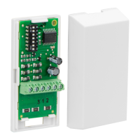
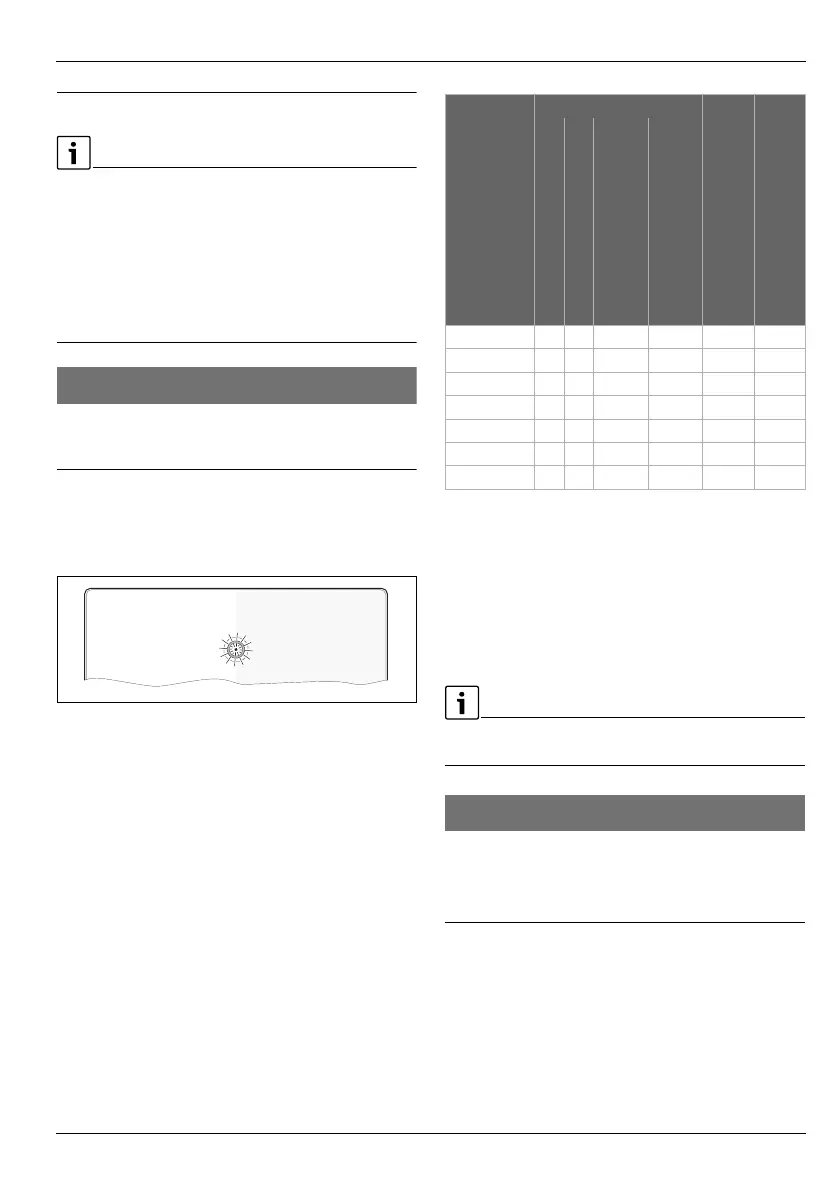
4.1 Setting the coding switch
Coding switch with On/Off indicator of the module and a status
display of the connected heat sources or modules:
Fig. 5 Coding switch with module status display, and a
status display of the connected heat sources or
modules
Table 7 Coding and function
4.2 Commissioning of the system and module
If a control unit is connected, start the automatic configuration
wizard.
NOTICE:
Danger of data loss in combination with MC 400
Follow the sequence during commissioning.
▶ First put heat source into operation with MU 100, then put
MC 400 into operation.
0 010 013 313-001
Coding Function of module
2nd solenoid valve activation
Fault output
Flow temperature control of the
heat source
Output control of the
heat source
Pump control via 0-10 V
Pump control via
PWM signal
0
1)
1) Off (delivered condition)
– – – – – –
1 – –
2 – –
3
2)
2) In the case of simple systems, which operate with the
standard settings, no control unit CW 400/RC310 is
necessary in positions 3 and 4. This is optional.
– – –
4
2)
– – –
5 – – – –
6-10
3)
3) Unused
– – – – – –
 Loading...