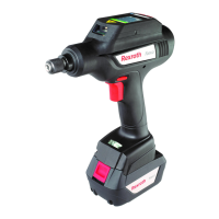
164/263 Bosch Rexroth AG | Tightening Technology
7.6.1 Message structure
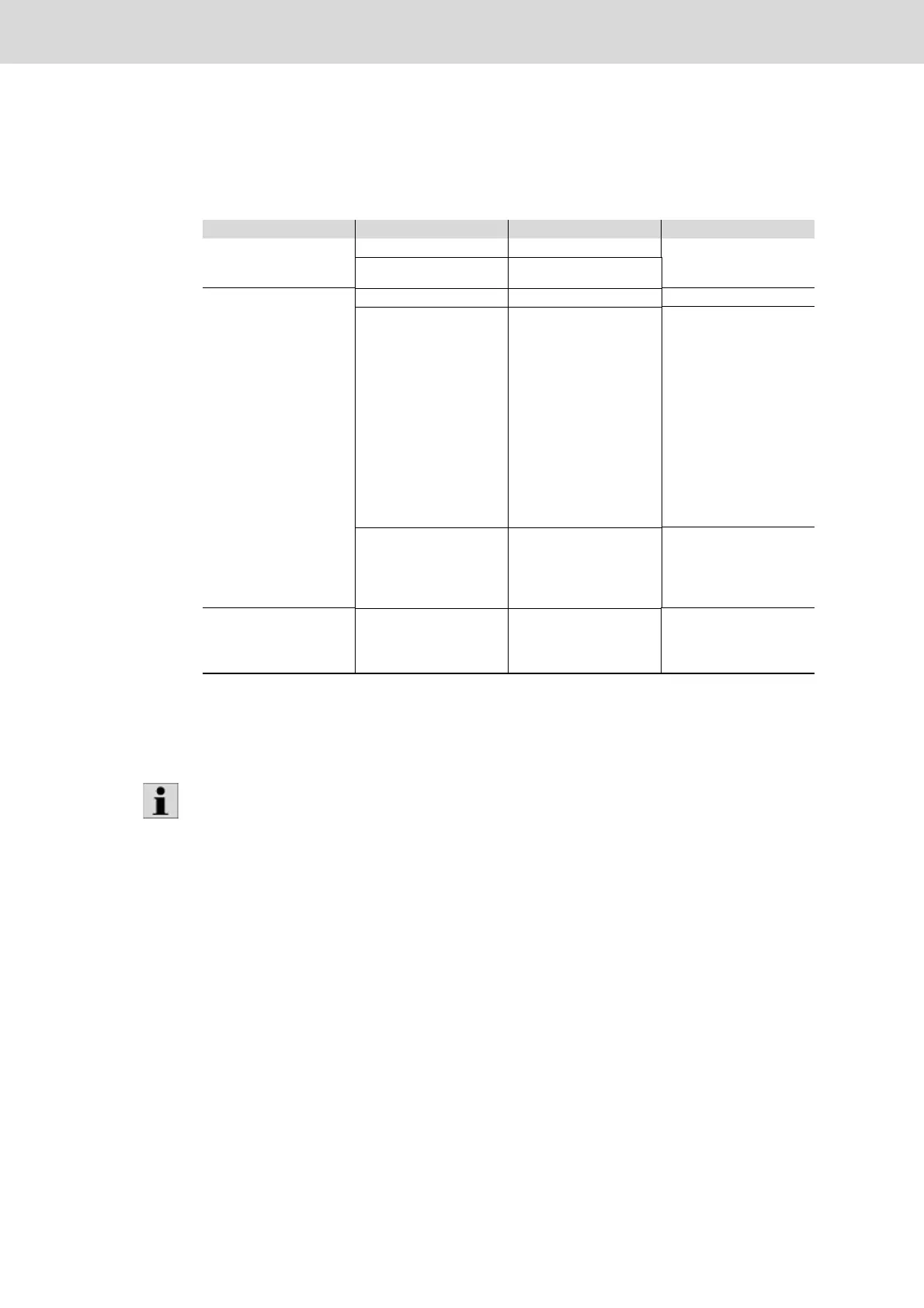
Table 7–50 shows the basic structure of a message of the Rexroth IPM Protocol.
Table 7–50: Rexroth IPM Protocol message structure
Message component Element Element description Remark
Header AFO AFO description For identification of a work
sequence (AFO) and/or
tightening position
Name AFO name
Data fields Steps Tightening steps
Actual values/
characteristics
1
1. If there is no actual value for a feature, e.g. because the corresponding monitoring function in the tightening pro-
gram is not activated, a so-called "actual dummy value" having the value -9999999 will be transferred. In the sub-
sequent evaluation on the IPM web interface, this pseudo measurement value can then be filtered out again.
Measured actual values like
– Torque (TA)
–Angle (AA)
– Gradient (GA)
–Time (TA)
– Torque threshold (SA)
Parameters belonging to
the actual values:
–TA:
TV, T+, T-, TS
– AA:
AV, A+, A--
–GA:
GV, G+, G-
–TA:
TV, T+
–SA:
without parameters
Set values/parameters Parameterized values from
KE/CS, set values and limit
values as well as parame-
ters from the database like
torque threshold set value
Parameters are clearly iden-
tified via the combination of
KE/CS, tightening channel
and tightening program
Graphs Graphs Filtered tightening result
graphs (graph filter) with
and without tightening
steps
Torque values related to data output from the Nexo cordless Wi-Fi nutrunner are rounded to two decimals
for transfer to the IPM communication partner. This may result in an error evaluation on the IPM commu-
nication partner. Please note that rounded values may result in error evaluations.