41
Disassembly Procedures
L1
®
Model II Power Stand Procedures
1. Leg Assembly Removal
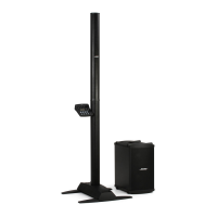
1.1 On a soft surface, place the
power stand upside down on its
top housing with the legs facing
upward.
1.2 With the power stand legs
closed, remove the four screws
indicated at right.
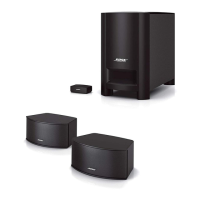
1.3 Open the power stand legs
by rotating the leg assembly
open. Remove the fourteen
remaining screws that secure
the leg assembly to the upper
housing.
1.4 Carefully lift off the leg
assembly. Unplug the amplifier
cable that connects to the line
array cavity. Unplug the green/
yellow ground wire from the AC Input PCB
at terminal E1A.
2. Input / Output Panel Assembly Removal
Note: This procedure removes the entire
input / output panel assembly with the circuit
boards attached. Procedures for removing
individual boards are below.
2.1 Perform procedure 1.
2.2 Unplug the wire harnesses at CON300L
and CON300B on the AC Input PCB.
CAUTION: During re-assembly, be sure to
dress the AC wiring so that it will clear the
leg mechanism internal moving parts. Failure
to do so will result in AC line voltage on the
leg assembly metal parts and present a
danger to end users. Be sure to perform the
Hi-Pot test in this manual before returning
the unit to a customer.
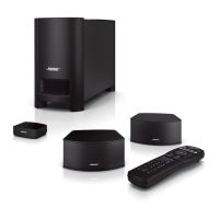
2.3 Unplug the wire harnesses at CN301B-B,
J301B, J303B, J302B, CN101, CN102,
J302L, J301L and J303L on the DSP PCB.
 Loading...