51
Appendix
L1
®
Model II Power Stand Test Cables
Note: In order to be able to properly test the L1 Model II Power Stand, you will need to make a
few test cables.
1. Powerstand Boot Test Cable
This test cable plugs into the boot connector of the L1
TM
Model II
Power Stand for all line array amplifier tests.
Parts needed:
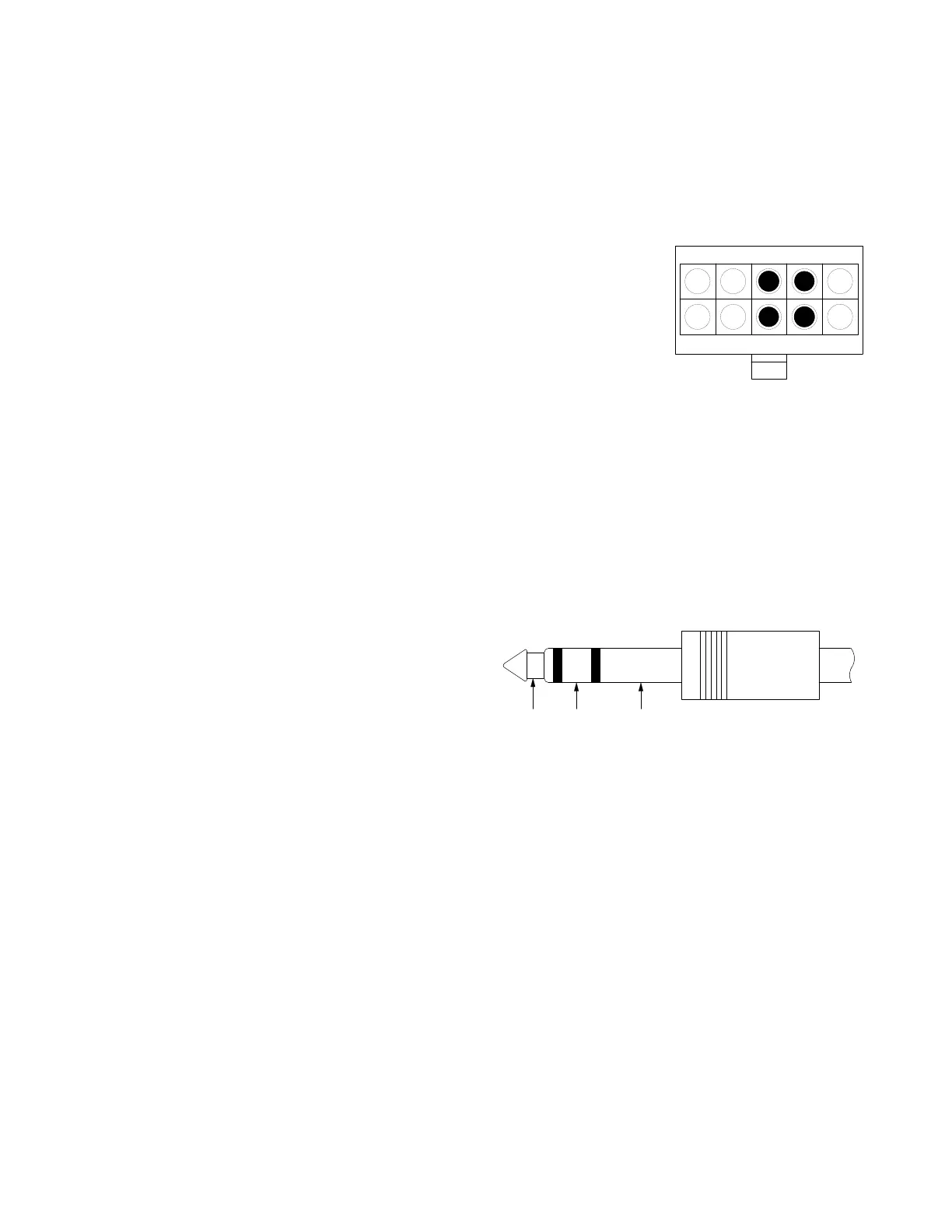
1 - 10 pin Molex female connector, Molex part number 39-01-3103
4 - Molex crimp-on pins for above connector
1 - dual banana jack
12 feet of 16 or 18AWG twisted pair wire
Cut the 12 foot length of twisted pair wire in half. Strip all of the
wires back about 1/4 inch. Crimp the molex pins onto the wires. The positive (+) side of the
twisted pair wires will go into pins 3 and 8 of the Molex connector. The negative (-) side of the
twisted pair wires will go into pins 4 and 9 of the Molex connector. Connect the wires that go to
pins 3 and 8 of the Molex connector to the positive (+) side of the dual banana jack. Connect the
wires that go to pins 4 and 9 of the Molex connector to the negative (-) side of the dual banana
jack.
2. Line Input 1/4" Phono Jack Test Cable
Parts needed:
1 - TRS 1/4" phono jack
1 - Dual banana jack
16 - 18 AWG shielded 3-wire cable, 6 feet
This cable is used to test the line input on
the power stand.
Connect the dual banana jack’s positive (+) connection to the tip connection of the 1/4" phono
jack. Connect the dual banana jack negative (-) connection to the ring connection of the 1/4"
phono jack. Connect the sleeve of the TRS jack to a single banana connector.
123 54
678910
Molex Connector Rear View
 Loading...