56
L1
®
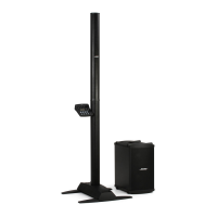
Model II Power Stand
The L1 Model II Power Stand houses input and output connectors, a DSP circuit board, two
amplifier circuit boards, and a receptacle for the L1 Cylindrical Radiator
®
.
L1 Model II power stand firmware can be updated when connected to a T1, then to a PC via
USB port. The PC software application is called the L1 updater. See Bose L1 Updater
Instructions.pdf on the Bose Musicians web site at http://www.bose.com/musicians for software
update instructions. Note: The L1 updater software is PC only. There is no Apple version.
1. DSP PCB
1.1 Input / Output Connectors
• AC mains input- IEC connector
• ¼” balanced analog input jack
• Bass Line Out – ¼” Line level bass signal output
• Bass Module Out – Neutrik
®
4 pin connector for B1 bass modules
• ToneMatch
®
port – Ethercon Input connector for the T1 ToneMatch Audio Engine, and
power output for the T1
1.2 Line Input
The ¼” Input accepts a line level signal. It is protected with spark gaps (SG1 and SG2) and
capacitors (C100, C112, C113) to chassis ground for ESD, and diodes (D10-1, D102) to the
supply rails for overvoltage. U100 performs differential to single-sided conversion, and VR1
provides a trim control. U104 converts back to a differential signal and buffers the codec input.
1.3 ToneMatch Input
The ethercon connector provides input and output for isolated S/PDIF – format digital signals.
Pins 3 and 6 are the signal input, they are fed through common-mode choke T101 for RF isola-
tion and T104 for electrical (DC) isolation. D110 clips the received signal, and it is passed
through a low pass filter (C181, C182, C183, R241, R242, R243) to U113, which acts as a
comparator with hysteresis.
U113 is also used to square the transmit S/PDIF signal output, which is passed through trans-
formers T103 and T100 to pins 1 and 2 on the ethercon connector.
Received S/PDIF signals are passed directly to the DSP. The DSP signal processing will be
described later in the document.
The DSP output is sent to the D/A converter (U108B). Channel A is used for the high frequency
signals for the line array, Channel B is for the bass signal. Each D/A output is filtered and
buffered (U105), then sent to the appropriate power amplifier.
1.4 Controls
• Power Switch - Switches the system on and off
• Trim Control - Adjusts the level of the analog input signal
Theory of Operation
 Loading...