EasyManua.ls Logo

Bose L1 II User Manual

Bose L1 II
70 pages
To Next Page IconTo Next Page
To Previous Page IconTo Previous Page
Page #6 background image
6
Product Description
The L1
®
Model II system – with ToneMatch
®
port
consists of the L1 model II power stand, the L1
model II Cylindrical Radiator
®
loudspeaker, and a
B1 bass module. The L1 model II system comes
with a padded carrying bag for each of its parts.
To expand your system and enhance perfor-
mance, you can add:
A second B1 bass module for bass guitar, kick
drum, or organ. Each power stand can power up
to two B1 bass modules.
A T1 ToneMatch audio engine for digital signal
processing, additional inputs and user-interface
control.
• A PackLite
®
power amplifier model A1 for
adding up to two more B1 bass modules to your
system.
L1 model II Cylindrical
Radiator
®
loudspeaker
L1 model II
power stand
L1 model II system with ToneMatch port Optional equipment
B1 bass
module
PackLite
power
amplifier
model A1
T1 ToneMatch
audio engine
Additional
B1 bass
module
System Components
The L1 Model II system is shipped in three separate cartons. Refer to the figure below.
Power stand carton Cylindrical Radiator
®
carton B1 bass module carton
L1 model II power stand
Carrying bag
AC power cord
Demonstration CD
Quick setup guide Owner’s guide
Product registration card
L1 model II
Cylindrical Radiator
®
loudspeaker
Carrying bags
B1 bass module
Carrying case
Bass module cable (blue 4-wire)
B1 bass module owner’s guide
L1
TM
Model II System
with ToneMatch
TM
port
Owner’s Guide
www.Bose.com/musicians
Top
Bottom
B1
Bass Module
Installation Guide
Question and Answer IconNeed help?

Do you have a question about the Bose L1 II and is the answer not in the manual?

Bose L1 II Specifications

General IconGeneral
BrandBose
ModelL1 II
CategoryControl Unit
LanguageEnglish

Summary

Safety Information

Warranty

Details the warranty coverage for the Power Stand, Radiator, and Bass Module.

Specifications

External Dimensions

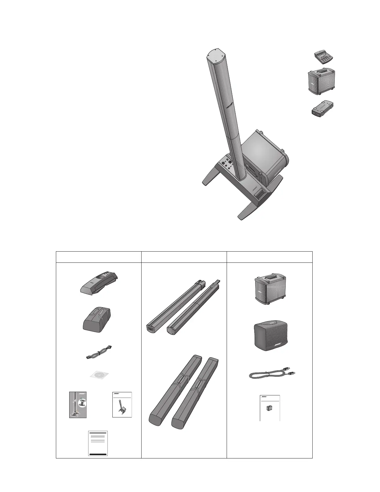
Provides physical dimensions for the Cylindrical Radiator, Power Stand, and Bass Module.

Weight

Lists the weight specifications for each component of the system.

Input / Output Panel Connections

Details the available input and output connectors on the power stand.

Electrical Specifications

Outlines electrical performance parameters like impedance and frequency response.

Specifications

Power Amplifiers

Specifies electrical characteristics for the power amplifier stages.

ESDS Device Handling

Part List Notes

Product Description

System Components

Setting Up the L1 Model II Power Stand

Assembling the L1 Model II Cylindrical Radiator Loudspeaker

Connecting the B1 Bass Module

L1 Model II Power Stand Input and Output Connectors, Controls

Setting the Analog Input Level on the L1 Model II Power Stand

Adding a T1 ToneMatch Audio Engine

Packaging Part List: L1 Model II Power Stand

Packaging Part List: L1 Model II Line Array

Packaging Part List: B1 Bass Module

Main Part List: Power Stand to Leg Assembly

Main Part List: L1 Model II Power Stand Upper Housing

Main Part List: L1 Model II Power Stand Cavity and Leg Assembly

Main Part List: L1 Model II Line Array

Main Part List: L1 Model II Line Array End Cap Assemblies

Main Part List: B1 Bass Module Exploded View

Electrical Part List: Input/Output PCB Assembly

Resistors

Lists resistors used on the Input/Output PCB, with reference designators and values.

Electrical Part List: Input/Output PCB Assembly

Resistors (continued)

Continues the list of resistors for the Input/Output PCB.

Capacitors

Lists capacitors used on the Input/Output PCB, with reference designators and values.

Electrical Part List: Input/Output PCB Assembly

Capacitors (continued)

Continues the list of capacitors for the Input/Output PCB.

Electrical Part List: Input/Output PCB Assembly

Capacitors (continued)

Continues the list of capacitors for the Input/Output PCB.

Electrical Part List: Input/Output PCB Assembly

Capacitors (continued)

Continues the list of capacitors for the Input/Output PCB.

Electrical Part List: Input/Output PCB Assembly

Capacitors (continued)

Continues the list of capacitors for the Input/Output PCB.

Electrical Part List: Input/Output PCB Assembly

Capacitors (continued)

Continues the list of capacitors for the Input/Output PCB.

Electrical Part List: Input/Output PCB Assembly

Capacitors (continued)

Continues the list of capacitors for the Input/Output PCB.

Electrical Part List: Input/Output PCB Assembly

Inductors

Lists inductors used on the Input/Output PCB.

Diodes

Lists diodes used on the Input/Output PCB.

Electrical Part List: Input/Output PCB Assembly

Transistors

Lists transistors used on the Input/Output PCB.

Integrated Circuits

Lists integrated circuits used on the Input/Output PCB.

Electrical Part List: Input/Output PCB Assembly

Integrated Circuits (continued)

Continues the list of integrated circuits for the Input/Output PCB.

Miscellaneous

Lists miscellaneous components for the Input/Output PCB.

Electrical Part List: Power Amplifier PCB Assembly

Resistors

Lists resistors used on the Power Amplifier PCB.

Electrical Part List: Power Amplifier PCB Assembly

Resistors (continued)

Continues the list of resistors for the Power Amplifier PCB.

Electrical Part List: Power Amplifier PCB Assembly

Resistors (continued)

Continues the list of resistors for the Power Amplifier PCB.

Capacitors

Lists capacitors used on the Power Amplifier PCB.

Electrical Part List: Power Amplifier PCB Assembly

Capacitors (continued)

Continues the list of capacitors for the Power Amplifier PCB.

Electrical Part List: Power Amplifier PCB Assembly

Capacitors (continued)

Continues the list of capacitors for the Power Amplifier PCB.

Inductors

Lists inductors used on the Power Amplifier PCB.

Diodes

Lists diodes used on the Power Amplifier PCB.

Electrical Part List: Power Amplifier PCB Assembly

Diodes (continued)

Continues the list of diodes for the Power Amplifier PCB.

Transistors

Lists transistors used on the Power Amplifier PCB.

Electrical Part List: Power Amplifier PCB Assembly

Integrated Circuits

Lists integrated circuits used on the Power Amplifier PCB.

Miscellaneous

Lists miscellaneous components for the Power Amplifier PCB.

AC Primary PCB Assembly Miscellaneous

Lists miscellaneous components for the AC Primary PCB.

Disassembly Procedures

L1 Model II Power Stand Procedures

Details procedures for disassembling the L1 Model II Power Stand.

Leg Assembly Removal

Steps to remove the leg assembly from the power stand.

Input / Output Panel Assembly Removal

Steps to remove the input/output panel assembly.

Disassembly Procedures

AC Input PCB Removal

Steps to remove the AC Input PCB from the power stand.

DSP PCB Removal

Steps to remove the DSP PCB from the power stand.

Disassembly Procedures

Amplifier Board Removal

Steps to remove the amplifier boards from the power stand.

Disassembly Procedures

Fan Removal

Steps to remove the cooling fan from the power stand.

Line Array Procedures

General procedures for disassembling the line array sections.

Upper Line Array Grille Removal

Steps to remove the grille from the upper line array section.

Disassembly Procedures

Driver Removal

Steps to remove the driver from the line array baffle.

Upper Line Array Top End Cap (#1) Removal

Steps to remove the top end cap of the upper line array.

Upper Line Array Bottom End Cap (#2) Removal

Steps to remove the bottom end cap of the upper line array.

Lower Line Array Top End Cap (#3) Removal

Steps to remove the top end cap of the lower line array.

Lower Line Array Bottom End Cap (#4) Removal

Steps to remove the bottom end cap of the lower line array.

Disassembly Procedures

Bass Module Procedures

Details procedures for disassembling the bass module.

Grille Removal

Steps to remove the grille from the bass module.

Bose Logo Removal

Steps to remove the Bose logo from the bass module grille.

Woofer Removal

Steps to remove the woofer from the bass module.

Input Panel Removal

Steps to remove the input panel from the bass module.

Test Procedures

L1 Model II Power Stand Tests

Overview of tests for the L1 Model II Power Stand.

Line Array Amplifier THD+N Test

Procedure to test Total Harmonic Distortion plus Noise for the line array amp.

Line Array Amplifier Noise Test

Procedure to measure output noise level for the line array amplifier.

Bass Module Amplifier THD+N Test

Procedure to test THD+N for the bass module amplifier.

Test Procedures

Bass Line Output Test

Tests the bass line output functionality and muting behavior.

L1 Model II System Sweep Test

Tests the system's audio output across a frequency range.

ToneMatch (M) Port Test

Tests the ToneMatch port connection and T1 Audio Engine operation.

Hi-Pot Test

Mandatory electrical safety test to check for shock hazards.

Test Procedures

Ground Bond Test

Ensures proper ground connection integrity for electrical safety.

L1 Model II Line Array Tests

Outlines tests specific to the L1 Model II Line Array.

Air Leak Test

Checks for air leaks around the line array enclosure and grille.

Transducer Rub and Tick Test

Checks for extraneous noises from the line array transducer.

Test Procedures

Transducer Phase Test

Verifies the correct phase of the line array transducer drivers.

Line Array Sweep Test

Tests the line array system's response to frequency sweeps.

B1 Bass Module Tests

Outlines tests specific to the B1 Bass Module.

Transducer Rub and Tick Test

Checks for extraneous noises from the bass module transducer.

Appendix

L1 Model II Power Stand Test Cables

Instructions for building custom test cables for the power stand.

Powerstand Boot Test Cable

Details parts and assembly for the power stand boot test cable.

Line Input 1/4" Phono Jack Test Cable

Details parts and assembly for the line input test cable.

Appendix

Bass Amplifier Output Test Cable

Details parts and assembly for the bass amplifier output test cable.

Appendix

L1 Model II Line Array Test Cables

Instructions for building custom test cables for line array sections.

Appendix

L1 Model II Power Stand EQ and Firmware Update Procedure

Guide for updating the EQ and firmware of the L1 Model II Power Stand.

Theory of Operation

L1 Model II Power Stand Overview

General description of the L1 Model II power stand's design.

DSP PCB Functionality

Explains the role and connections of the Digital Signal Processor PCB.

Power Stand Inputs, Outputs, and Controls

Details the connectors, signal paths, and controls on the power stand.

Theory of Operation

Indicators

Explains the meaning of the Power/Fault and Signal/Clip indicators.

Signal Processing

Illustrates the audio processing chain from input to output.

Amplifier Controls

Describes DSP control over amplifiers and fan operation.

Theory of Operation

Amplifier Board Design and Power

Covers amplifier board architecture, variants, DC power, and input filtering.

Theory of Operation

Converter Section Circuitry

Details the DC-to-DC converter and its operating frequency.

Amplifier Section

Explains the amplifier's gain, power output, and configuration.

Theory of Operation

Output Power Limiting

Illustrates how output power is limited by zobel shutdown based on frequency.

Theory of Operation

Protection Mechanism Summary

Summarizes the different protection mechanisms and their detection methods.

L1 Model II Cylindrical Radiator Loudspeaker

Theory of Operation

Bass Module B1

Explains the function and connectivity of the B1 Bass Module.

Circuit Board Layout Diagrams

AC Input PCB Topside Etch and Layout

Shows the topside layout and etch pattern of the AC Input PCB.

Circuit Board Layout Diagrams

DSP PCB Topside Etch and Layout

Shows the topside layout and etch pattern of the DSP PCB.

Circuit Board Layout Diagrams

DSP PCB Bottom Silk and Internal Layer 1

Shows the bottom silk screen and internal layer 1 of the DSP PCB.

Circuit Board Layout Diagrams

DSP PCB Bottom Silk and Internal Layer 2

Shows the bottom silk screen and internal layer 2 of the DSP PCB.

Circuit Board Layout Diagrams

DSP PCB Bottom Silk and Etch

Shows the bottom silk screen and etch pattern of the DSP PCB.

Circuit Board Layout Diagrams

Amplifier/SMPS PCB Topside Etch Layout

Shows the topside layout and etch pattern of the Amplifier/SMPS PCB.

Amplifier/SMPS PCB Internal Etch Layer 1 Layout

Shows the internal layer 1 layout and etch pattern of the Amplifier/SMPS PCB.

Circuit Board Layout Diagrams

Amplifier/SMPS PCB Internal Etch Layer 2 Layout

Shows the internal layer 2 layout and etch pattern of the Amplifier/SMPS PCB.

Amplifier/SMPS PCB Bottom Etch Layout

Shows the bottom layout and etch pattern of the Amplifier/SMPS PCB.

Service Manual Revision History

Related product manuals