62
Theory of Operation
Bass Module B1
The B1 bass module is a dedicated passive unit that houses two 5 1/4” drivers. The input is via
one of two 4-pole Neutrik
®
Speakon
®
connectors on the rear panel. Both of these inputs are
paralleled, allowing you to jumper multiple bass modules together. There are no crossover or
protection ciricuit components located on the input panel. All EQ and protection is performed in
the PS1 power stand.
Pins 1+ and 1- of the input connector are used to apply the input signal to the bass module. Pins
2+ and 2- are connected to a 10k ohm resistor on the bass module rear panel PCB. This allows
the power stand to detect how many bass modules are connected to it from the Bass Out con-
nector.
If the power stand sees a 10k resistance, it knows that there is only one bass module connected
and adjusts the output level and EQ accordingly. If it sees 5k ohm resistance, it then knows that
there are 2 bass modules connected, and again, adjusts the output level and EQ accordingly.
If the power stand sees an infinite resistance, it knows that there is no bass module connected
and adjusts accordingly.
The woofers in the bass module are replaceable. The input panel, grille and Bose
®
logo are also
replaceable.
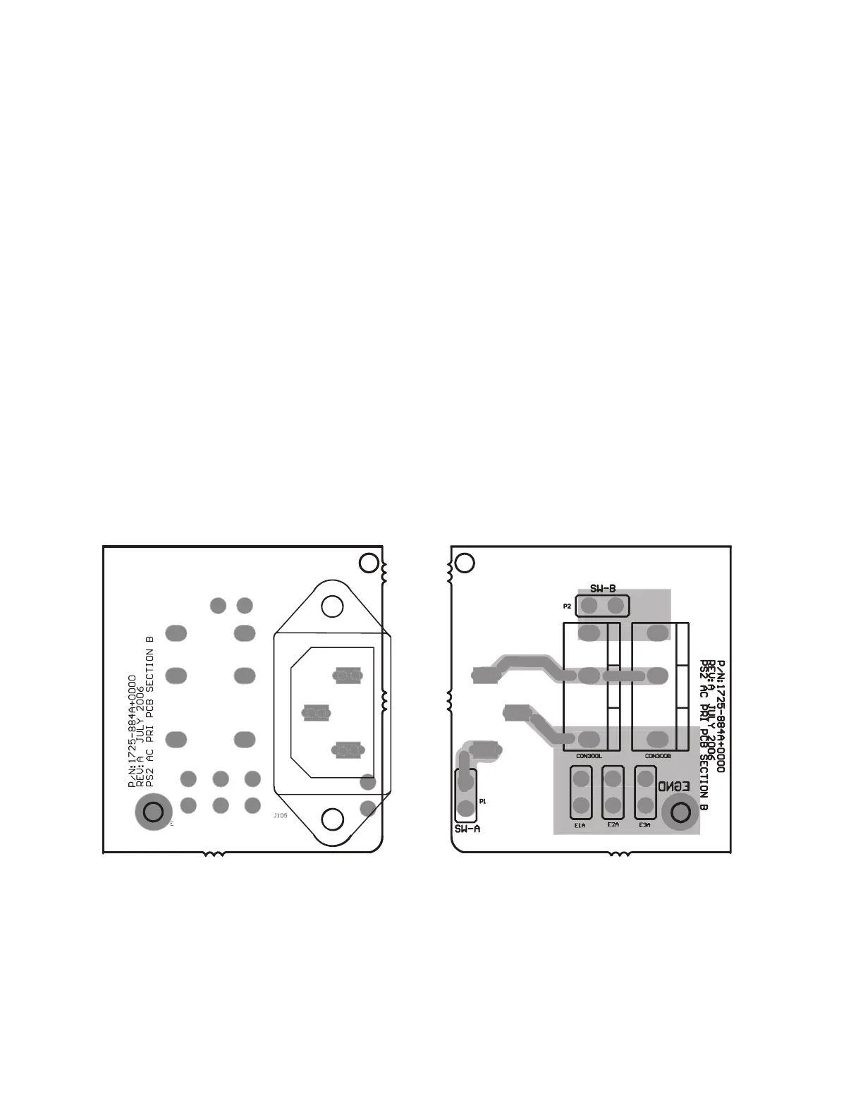
Figure 11. AC Input PCB
Topside Etch and Layout
Figure 12. AC Input PCB
Bottom Etch and Layout
Circuit Board Layout Diagrams
 Loading...