47
Test Procedures
L1
®
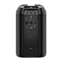
Model II Power Stand Tests
Equipment Required
• dB Meter
• Digital Multi-meter
• Audio Signal Generator
• Distortion Meter
• 2 - 4 Ohm, 250 Watt Load Resistors
• Neutrik
®
Speakon
®
NL4 plug
• Test cables, see Appendix
Test Setup
For the following tests, connect a Neutrik
®
Speakon
®
NL4 plug to the bass module out
jack on the power stand input/output panel.
Short pins 2+ and 2- on the plug together.
This will put the power stand into test mode.
1. Line Array Amplifier THD+N Test
1.1 Connect a power stand boot test cable to
the line array output jack located in the line
array cavity well in the power stand. Termi-
nate the cable with a 4 ohm, 250 Watt load
resistor.
1.2 Set the power stand trim knob to mid-
point. Using a TRS input cable, apply
a balanced 3mVrms, 1 kHz input signal to
the analog input jack on the power stand
input panel.
1.3 Slowly increase the input level from -
50dBV to 500mVrms. While increasing the
input level, measure the THD+N level across
the load resistor. Verify that the noise level is
<0.05% @ -20dBV.
2. Line Array Amplifier Noise Test
2.1 Connect a power stand boot test cable to
the line array output jack located in the line
array cavity well in the power stand. Termi-
nate the cable with a 4 ohm, 250 Watt load
resistor.
2.2 Set the power stand trim knob to mid-
point. Using a shorted TRS plug, short the
analog input jack on the power stand input
panel.
2.3 Measure the output noise level at the
load resistor. It should be <0.3mVrms, A-
Weighted.
3. Bass Module Amplifier THD+N Test
3.1 Connect a Bass Amplifier Output Test
Cable to the bass module output jack
located on the input/output panel on the
power stand. Terminate the 1+ and 1- leads
on the cable with a 4 ohm, 250 Watt load
resistor. Short the 2+ and 2- leads together
to put the power stand into test mode.
3.2 Set the power stand trim knob to mid-
point. Using a TRS input cable, apply a
balanced 3mV rms, 1 kHz input signal to the
analog input jack on the power stand input
panel.
3.3 Slowly increase the input level from
3mVrms to 500mVrms. While increasing the
input level, measure the THD+N level
across the load resistor. Verify that the
noise level is <0.05% @ 100mVrms.
4. Bass Module Amplifier Noise Test
4.1 Connect a Bass Amplifier Output Test
Cable to the bass module output jack
located on the input/output panel on the
power stand. Terminate the 1+ and 1- leads
on the cable with a 4 ohm, 250 Watt load
resistor. Short the 2+ and 2- leads together
to put the power stand into test mode.
4.2 Set the power stand trim knob to mid-
point. Using a shorted TRS plug, short the
analog input jack on the power stand input
panel.
4.3 Measure the output noise level at the
load resistor. It should be <0.3 mVrms,
A-Weighted.
Note: The Neutrik
®
Speakon
®
NL4 test plug
is not used for the following tests.

 Loading...
