3-68
Confidential
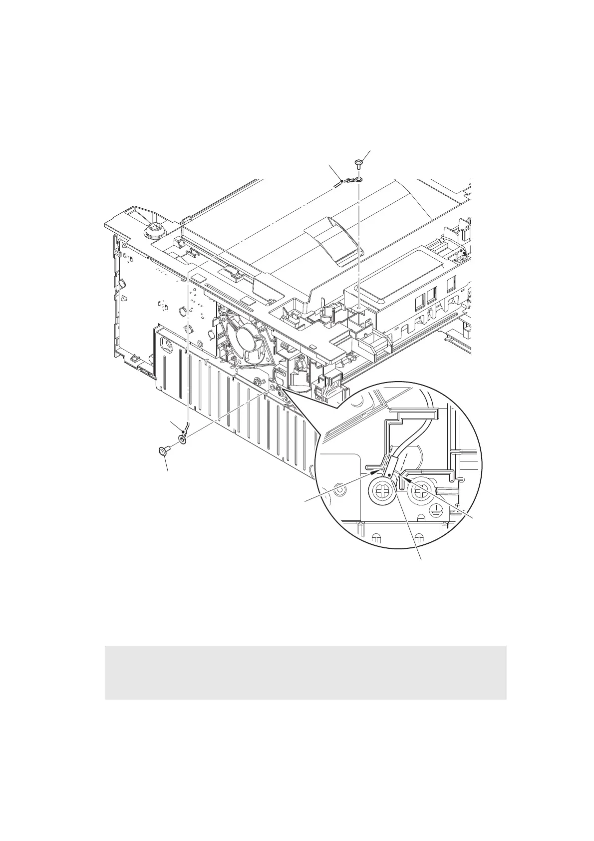
9.16 Modem flat cable / Modem PCB ASSY
(1) Remove the two Screw cup M3x8 (black) screws, and release the Modem ground harness
LVPS from the securing fixtures.
Fig. 3-61
Harness routing: Refer to “7. Modem PCB ASSY (LVPS side)”.
Assembling Note:
• Make sure that the Terminal of Modem ground harness LVPS is located between the
Rib A and the Rib B as shown in the figure above.
Screw cup M3x8 (black)
Modem ground harness LVPS
Rib A
Rib B
Terminal of Modem ground
harness LVPS
Modem ground
harness LVPS
Screw cup M3x8 (black)
 Loading...