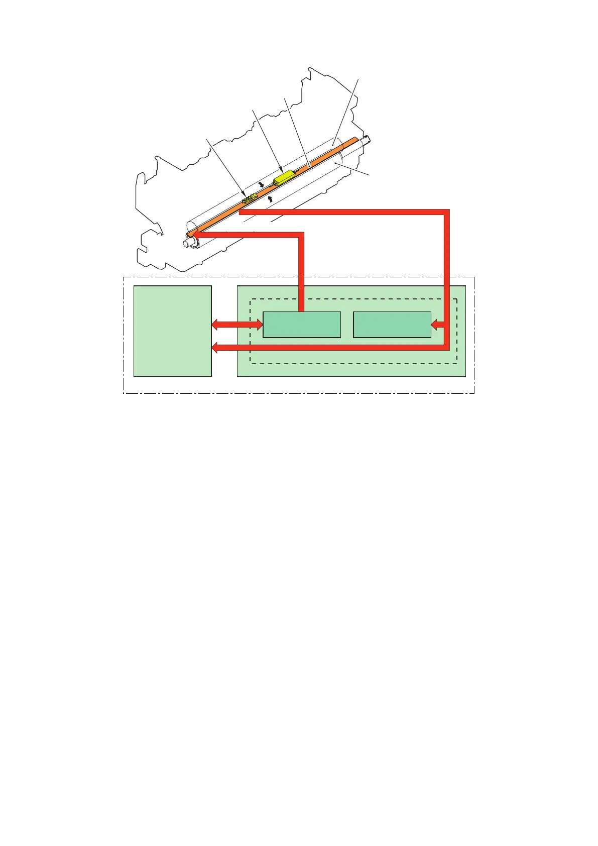
The Figure below shows the configuration of the fixing control circuit.
FIXING TEMPERA TURE signal
Pressure roller
FIXNG HEATER CONTROL signal
Fixing film
Fixing heater
control circuit
Fixing heater
safety circuit
DC controller
Low-voltage power supply unit
Engine controller
Fixing control circuit
H1
TP1
TH1
• Fixing heater (H1): Heats the fixing film
• Thermistor (TH1): Detects fixing temperature (Contact type)
• Thermoswitch (TP1):Prevents an abnormal temperature rise of the fixing heater (Contact type)
These temperature controls in the fixing unit are performed by the fixing heater control circuit and the fixing heater safety circuit
according to the commands from the DC controller.
■ Fixing temperature control
The fixing temperature control maintains the temperature of the fixing heater at its targeted temperature.
Block diagram of this control is shown below.
2. Technology
23
 Loading...