9
ENG
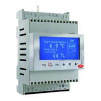
“EVD evolution” +030222041 - rel. 1.0 - 01.06.2008
INSTALLATION 2.
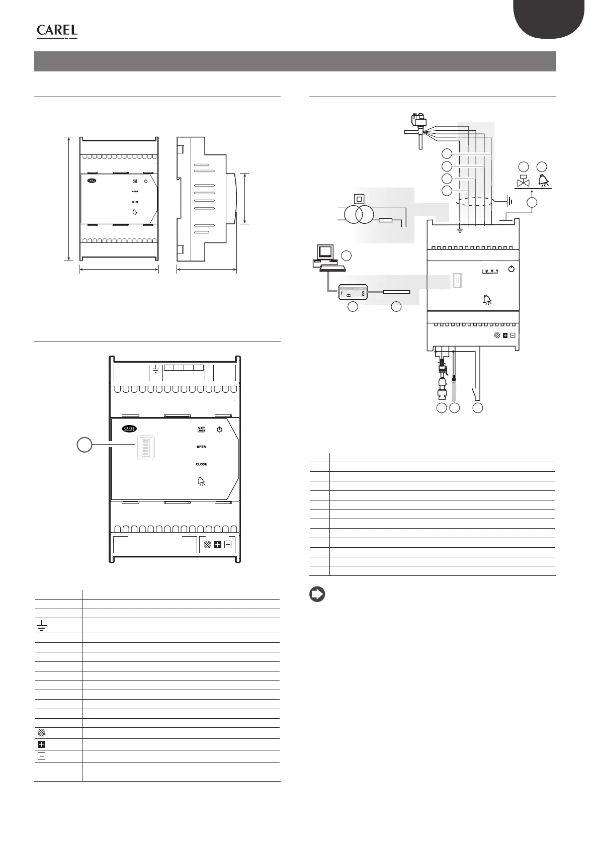
DIN rail assembly and dimensions2.1
EVD evolution is supplied with screen-printed connectors to simplify
wiring. The shield is connected with a spade terminal.
VBAT
G0
G
E
X
V connectionPower Supply Relay
NO 1
COM 1
4231
GND
V REF
S1
S2
S3
S4
DI1
DI2
Analog – Digital Input Network
GND Tx/Rx
EVD evoluti on
70 60
110
45
Fig. 2.a
Description of the terminals2.2
VBAT
G0
G
E
X
V connectionPower Supply Relay
NO 1
COM 1
4231
GND
V REF
S1
S2
S3
S4
DI1
DI2
Analog – Digital Input Network
GND Tx/Rx
EVD evolution
aa
Fig. 2.b
Terminal Description
G, G0 Power supply
VBAT Emergency power supply
Functional earth
1,3,2,4 Stepper motor power supply
COM1, NO1 Alarm relay
GND Earth for the signals
VREF Power to active sensors
S1 Sensor 1 (pressure) or 4 to 20 mA external signal
S2 Sensor 2 (temperature) or 0 to 10 V external signal
S3 Sensor 3 (pressure)
S4 Sensor 4 (temperature)
DI1 Digital input 1
DI2 Digital input 2
Terminal for tLAN, pLAN, RS485, Modbus® connection
Terminal for tLAN, pLAN, RS485, Modbus® connection
Terminal for pLAN, RS485, Modbus® connection
aa porta seriale di servizio (rimuovere il coperchio per potervi
accedere)
Tab. 2.a
Connection diagram - superheat control2.3
G
G0
G
G0
VBAT
COM1
NO1
1
3
2 4
NET
OPEN
CLOSE
Tx/RxGND
DI1
S4
S3
S2
S1
GND
DI2
VREF
2 AT
24 Vac
230 Vac
30VA
shield
EVD4
PC
EVD4 service USB adapter
4
S
4
2
3
CAREL E
X
V
1
6 7
8 9 10
11
12 13
5
Fig. 2.c
Key:
1 green
2 yellow
3 brown
4 white
5 personal computer for confi guration
6 USB/tLAN converter
7 adapter
8 ratiometric pressure transducer - evaporation pressure
9 NTC suction temperature
10 digital input 1 to enable control
11 free contact (up to 230 Vac)
12 solenoid valve
13 alarm signal
Note:
the use of the driver for the superheat control requires the use of the •
evaporation pressure sensor S1 and the suction temperature sensor S2,
which will be fi tted after the evaporator, and digital input 1 to enable
control. As an alternative to digital input 1, control can be enabled via
remote signal (tLAN, pLAN, RS485). For the positioning of the sensors
relating to other applications, see the chapter on “Control”;
inputs S1, S2 are programmable and the connection to the terminals •
depends on the setting of the parameters. See the chapters on
“Commissioning” and “Functions”;
pressure sensor S1 in the diagram is ratiometric. See the general •
connection diagram for the other electronic sensors, 4 to 20 mA or
combined.
 Loading...