10
ENG
“EVD evolution” +030222041 - rel. 1.0 - 01.06.2008
Installation2.4
For installation proceed as follows, with reference to the wiring
diagrams:
connect the sensors and power supply: the sensors can be installed 1.
a maximum distance of 10 metres away from the controller, as long
as shielded cables are used with minimum cross-section of 1 mm²
(connect only one end of the shield to the earth in the electrical
panel);
connect any digital inputs, maximum length 30 m;2.
connect the power cable to the valve motor: recommended 4-wire 3.
shielded cable, AWG 18/22, Lmax=10 m;
carefully evaluate the maximum capacity of the relay output specifi ed 4.
in the chapter “Technical specifi cations”;
program the driver, if necessary: see the chapter “User interface”;5.
connect the serial network, if featured: follow to the diagrams below 6.
for the earth connection.
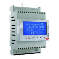
Case 1: multiple drivers connected in a network powered by the same
transformer. Typical application for a series of drivers inside the same
electrical panel.
G
G0
VBAT
COM1
NO1
1
3
2
4
G
G0
VBAT
COM1
NO1
1
3
2
4
2 AT
G
G0
VBAT
COM1
NO1
1
3
2
4
2 AT
2 AT
230 Vac
24 Vac
pCO
Fig. 2.d
Case 2: multiple drivers connected in a network powered by diff erent
transformers (G0 not connected to earth). Typical application for a series
of drivers in diff erent electrical panels.
G
G0
VBAT
COM1
NO1
1
3
2
4
G
G0
VBAT
COM1
NO1
1
3
2
4
G
G0
VBAT
COM1
NO1
1
3
2
4
2 AT
230 Vac
24 Vac
2 AT
230 Vac
24 Vac
2 AT
230 Vac
24 Vac
pCO
Fig. 2.e
Case 3: multiple drivers connected in a network powered by diff erent
transformers with just one earth point. Typical application for a series of
drivers in diff erent electrical panels.
G
G0
VBAT
COM1
NO1
1
3
2
4
G
G0
VBAT
COM1
NO1
1
3
2
4
G
G0
VBAT
COM1
NO1
1
3
2
4
2 AT
230 Vac
24 Vac
2 AT
230 Vac
24 Vac
2 AT
230 Vac
24 Vac
pCO
Fig. 2.f
Important: avoid installing the driver in environments with the
following characteristics:
relative humidity greater than the 90% or condensing;•
strong vibrations or knocks;•
exposure to continuous water sprays;•
exposure to aggressive and polluting atmospheres (e.g.: sulphur •
and ammonia fumes, saline mist, smoke) to avoid corrosion and/or
oxidation;
strong magnetic and/or radio frequency interference (avoid installing •
the appliances near transmitting antennae);
exposure of the driver to direct sunlight and to the elements in •
general.
Important: When connecting the driver, the following warnings
must be observed:
incorrect connection to the power supply may seriously damage the •
driver;
use cable ends suitable for the corresponding terminals. Loosen each •
screw and insert the cable ends, then tighten the screws and lightly
tug the cables to check correct tightness;
separate as much as possible (at least 3 cm) the sensor and digital •
input cables from the power cables to the loads so as to avoid possible
electromagnetic disturbance. Never lay power cables and sensor
cables in the same conduits (including those in the electrical panels);
avoid installing the sensor cables in the immediate vicinity of power •
devices (contactors, circuit breakers, etc.). Reduce the path of the sensor
cables as much as possible and avoid enclosing power devices;
avoid powering the driver directly from the main power supply in the •
panel if this supplies diff erent devices, such as contactors, solenoid
valves, etc., which will require a separate transformer.
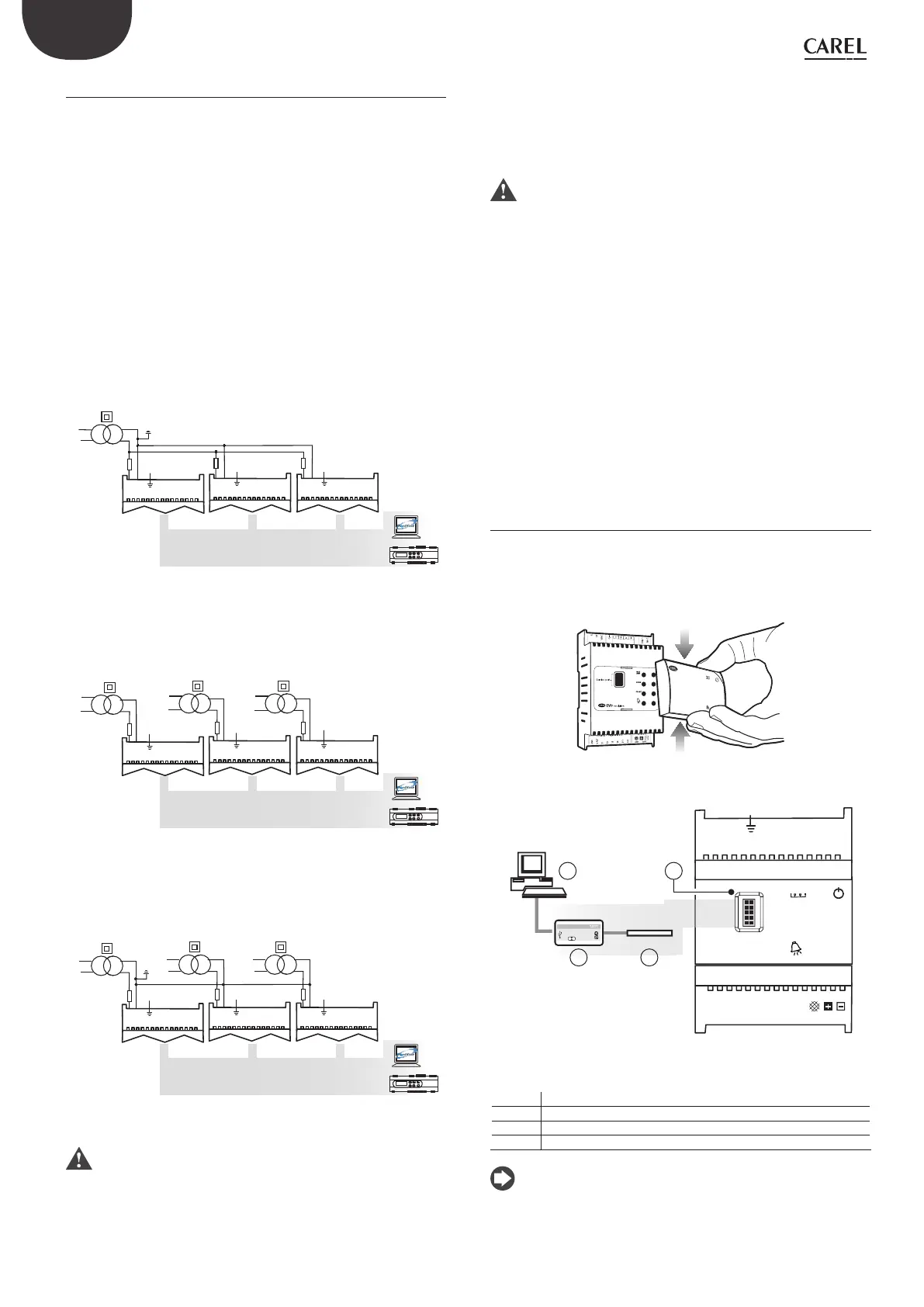
Connecting the USB-tLAN converter2.5
remove the LED board cover by pressing on the fastening points;•
plug the adapter into the service serial port;•
connect the adapter to the converter and then this in turn to the •
computer.
press
press
OPEN
CLOSE
EVD
evolution
Fig. 2.g
G
G0
VBAT
COM1
NO1
1
3
2 4
NET
OPEN
CLOSE
Tx/RxGND
DI1
S4
S3
S2
S1
GND
DI2
VREF
EVD4
PC
EVD4 service USB adapter
4
3 2
4 1
Fig. 2.h
Key:
1 service serial port
2 adapter
3 USB/tLAN converter
4 personal computer
Note: when using the service serial port connection, the VPM
program can be used to confi gure the driver and update the driver
and display fi rmware, downloadable from http://ksa.carel.com.
See appendix 1.
 Loading...