13
ENG
“EVD evolution” +030222041 - rel. 1.0 - 01.06.2008
USER INTERFACE3.
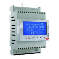
The user interface consists of 5 LEDs that display the operating status, as
shown in the table:
Fig. 3.a
Legenda:
LED ON OFF Flashing
NET Connection available No connection Communication
error
OPEN Opening valve - Driver disabled (*)
CLOSE Closing valve - Driver disabled (*)
Active alarm - -
Driver powered Driver not powered -
Tab. 3.a
(*) Awaiting completion of the initial confi guration
Assembling the display board 3.1
(accessory)
The display board, once installed, is used to perform all the confi guration
and programming operations on the driver. It displays the operating status,
the signifi cant values for the type of control that the driver is performing
(e.g. superheat control), the alarms, the status of the digital inputs and
the relay output. Finally, it can save the confi guration parameters for one
driver and transfer them to a second driver (see the procedure for upload
and download parameters).
For installation:
remove the cover, pressing on the fastening points;•
fi t the display board, as shown;•
the display will come on, and if the driver is being commissioned, the •
guided confi guration procedure will start.
Fig. 3.b
Important: the driver is not activated if the confi guration procedure
has not been completed.
The front panel now holds the display and the keypad, made up of 6
buttons that, pressed alone or in combination, are used to perform all the
confi guration and programming operations on the driver.
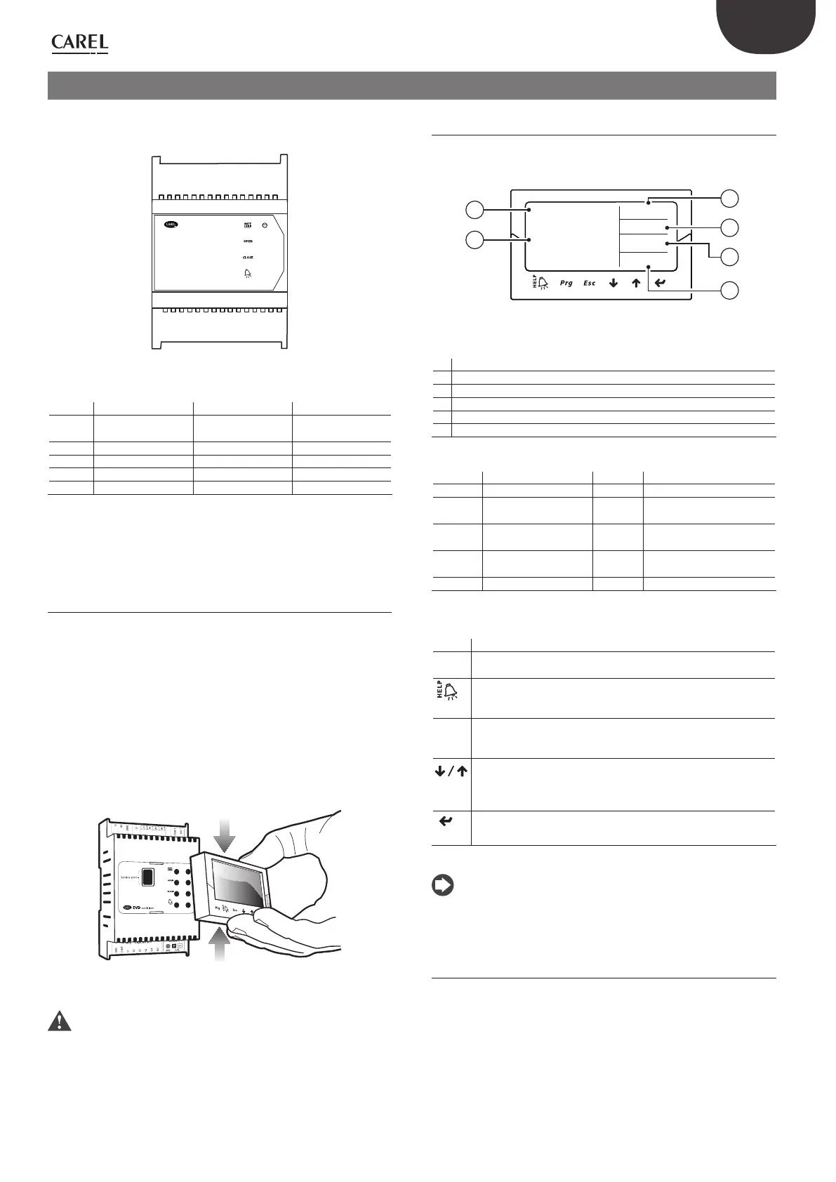
Display and keypad3.2
The graphic display shows 2 system variables, the control status of the
driver, the activation of the protectors, any alarms and the status of the
relay output.
Hjgg^hXVaYVb#
)#.@
6eZgijgV
kVakdaV
))
DC
BDE
6A6GB
""GZaZ
1
2
3
4
5
6
Fig. 3.c
Key:
1 1st variable displayed
2 2nd variable displayed
3 relay status
4 alarm (press “HELP”)
5 protector activated
6 control status
Display writings
Control status Protection active
ON Operation LowSH Low superheat
OFF Standby LOP Low evaporation tempe-
rature
POS Positioning MOP High evaporation tempe-
rature
WAIT Wait HiTcond High condensing tempe-
rature
CLOSE Closing
Tab. 3.b
Keypad
Button Function
Prg opens the screen for entering the password to access program-
ming mode.
if in alarm status, displays the alarm queue;•
in the “Manufacturer” level, when scrolling the parameters, shows •
the explanation screens (Help).
Esc exits the Programming (Service/Manufacturer) and Display
•
modes;
after setting a parameter, exits without saving the changes.•
UP/
DOWN
navigates the display screens;
•
increases/decreases the value.•
Enter
switches from the display to parameter programming mode;
•
confi rms the value and returns to the list of parameters.•
Tab. 3.c
Note: the variables displayed as standard can be selected by
confi guring the parameters “Variable 1 on display” and “Variable 2 on
display” accordingly. See the list of parameters.
Display mode (display)3.3
Display mode is used to display the useful variables showing the operation
of the system.
The variables displayed depend on the type of control selected.
press Esc to switch to the standard display;1.
press UP/DOWN: the display shows a graph of the superheat, 2.
the percentage of valve opening, the evaporation pressure and
temperature and the suction temperature variables;
press UP/DOWN: the variables are shown on the display;3.
press Esc to exit display mode.4.
 Loading...