35
ENG
“EVD evolution” +030222041 - rel. 1.0 - 01.06.2008
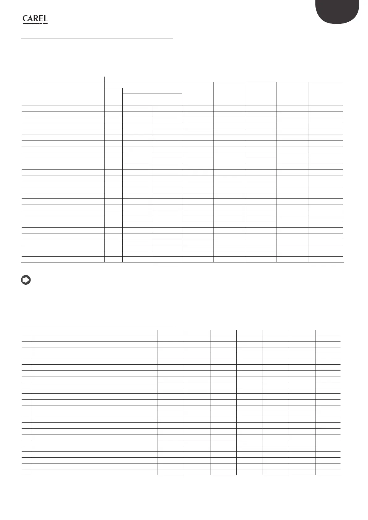
Variables shown on the display8.2
The table below shows the variables available in display mode, depending
on the setting of the “Main control” and “Auxiliary control” parameters:
press the UP/DOWN button to enter display mode;•
press the DOWN button to move to the next variable/screen;•
press Esc to return to the standard display.•
Main control
Variable displayed Superheat control Transcritical
CO
2
Hot gas
bypass /
temperature
Hot gas
bypass /
pressure
EPR back-
pressure
Analogue
positioning
Auxiliary control
HiTcond Modulating
thermostat
Valve opening(%) ••••••••
Valve position (step) ••••••••
Current cooling capacity unità ••••••••
Control set point •••••
Superheat •••
Suction temperature •••
Evaporation temperature •••
Evaporation pressure •••
Condensing temperature •
Condensing pressure •
Modulating thermostat temperature •
EPR pressure (back pressure) •
Hot gas bypass pressure •
Hot gas bypass temperature •
CO
2
gas cooler outlet temperature •
CO
2
gas cooler outlet pressure •
CO
2
gas cooler pressure set point •
Sensor S1 reading ••••••••
Sensor S2 reading ••••••••
Sensor S3 reading ••••••••
Sensor S4 reading ••••••••
4 to 20 mA input value •
0 to 10 Vdc input value •
Status of digital input DI1(*) ••••••••
Status of digital input DI2(*) ••••••••
EVD firmware version ••••••••
Display firmware version ••••••••
Tab. 8.b
(*) Digital input status: 0= open, 1= closed.
Note: the readings of sensors S1, S2, S3, S4 are always displayed,
regardless of whether or not the sensor is connected.
Variables only accessible via serial link8.3
Description Default Min Max Type CAREL SVP Modbus® R/W
Sensor S1 reading 0 -20 (-290) 200 (2900) A 1 0 R
Sensor S2 reading 0 -60 (-870) 200 (392) A 2 1 R
Sensor S3 reading 0 -20 (-290) 200 (2900) A 3 2 R
Sensor S4 reading 0 -60 (-76) 200 (392) A 4 3 R
Suction temperature 0 -60 (-76) 200 (392) A 5 4 R
Evaporation temperature 0 -60 (-76) 200 (392) A 6 5 R
Evaporation pressure 0 -20 (-290) 200 (2900) A 7 6 R
Hot gas bypass temperature 0 -60 (-76) 200 (392) A 8 7 R
EPR pressure (back pressure) 0 -20 (-290) 200 (2900) A 9 8 R
Superheat 0 -40 (-72) 180 (324) A 10 9 R
Condensing pressure 0 -20 (-290) 200 (2900) A 11 10 R
Condensing temperature 0 -60 (-76) 200 (392) A 12 11 R
Modulating thermostat temperature 0 -60 (-76) 200 (392) A 13 12 R
Hot gas bypass pressure 0 -20 (-290) 200 (2900) A 14 13 R
CO
2
gas cooler outlet pressure 0 -20 (-290) 200 (2900) A 15 14 R
CO
2
gas cooler outlet temperature 0 -60 (-76) 200 (392) A 16 15 R
Valve opening 0 0 100 A 17 16 R
CO2 gas cooler pressure set point 0 -20 (-290) 200 (2900) A 18 17 R
4 to 20 mA input value 4 4 20 A 19 18 R
0 to 10 V input value 0 0 10 A 20 19 R
Control set point 0 -60 (-76) 200 (392) A 21 20 R
Driver firmware version 0 0 10 A 25 24 R
Valve position 0 0 9999 I 4 131 R
Current unit cooling capacity 0 0 100 I 7 134 R/W
 Loading...