38
ENG
“EVD evolution” +030222041 - rel. 1.0 - 01.06.2008
Type of alarm Cause of alarm LED Display Relay Reset Effect on control Checks/ solutions
EEEPROM dama-
ged
EEPROM for
operating and/or
unit parameters
damaged
red alarm
LED
ALARM flashing Depends on
configuration
parameter
Replace dri-
ver/Contact
service
Total shutdown Replace the driver/Contact service
EEV motor error Valve motor fault red alarm
LED
ALARM flashing Depends on
configuration
parameter
automatic Interruption Check the connections and the con-
dition of the motor
pLAN error (EVD
pLAN only)
pLAN network
communication
error
green
NET LED
flashing
ALARM flashing Depends on
configuration
parameter
automatic Control based
on ID1
Check the network address settings
pLAN network
connection error
NET LED
off
ALARM flashing Depends on
configuration
parameter
automatic Control based
on ID1
Check the connections and that the
pCO is on and working
LAN error ( EVD
tLAN RS485/Mo-
dBus)
Network commu-
nication error
NET LED
flashing
No message No change automatic No effect Check the network address settings
Connection error NET LED
off
No message No change automatic No effect Check the connections and that the
pCO is on and working
Tab. 9.a
Alarm relay conguration9.2
The relay contact is open when the driver is not powered.
During normal operation, it can be disabled (and thus will be always
open) or configured as:
alarm relay: during normal operation, the relay contact is closed, and •
opens when any alarm is activated. It can be used to switch off the
compressor and the system in the event of alarms.
solenoid valve relay: during normal operation, the relay contact is •
closed, and is open only in standby. There is no change in the event
of alarms.
solenoid valve relay + alarm: during normal operation, the relay contact •
is closed, and opens in standby and/or for LowSH, MOP, HiTcond
and low suction temperature alarms. This is because following such
alarms, the user may want to protect the unit by stopping the flow of
refrigerant or switching off the compressor.
The LOP alarm is excluded, as in the event of low evaporation temperature
closing the solenoid valve would worsen the situation.
Parameter/description Def.
Relay configuration:
Disabled
Alarm relay (open when alarm active)
Solenoid valve relay (open in standby)
Valve relay +alarm (open in standby & control alarms)
Alarm
relay
Tab. 9.b
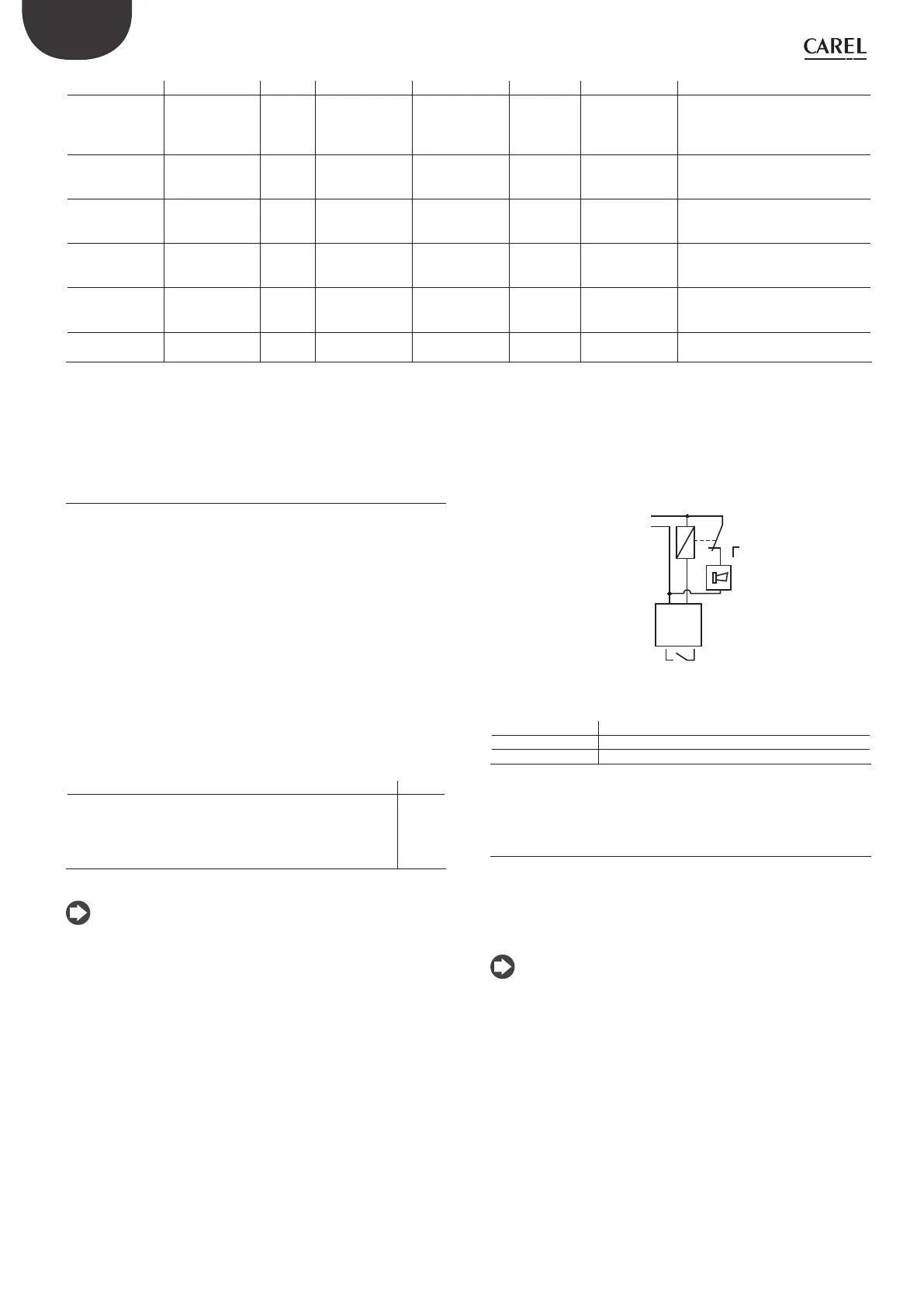
Note: if configured as an alarm relay, to send the alarm signal to a
remote device (siren, light), connect a relay to the output, according to
the following diagram:
Fig. 9.d
Key:
L Phase
N Neutral
COM1, NO1 Alarm relay output
Sensor alarms9.3
The sensor alarms are part of the system alarms. When the value measured
by one of the sensors is outside of the field defined by the parameters
corresponding to the alarm limits, an alarm is activated. The limits can be
set independently of the range of measurement. Consequently, the field
outside of which the alarm is signalled can be restricted, to ensure greater
safety of the controlled unit.
Note:
the alarm limits can also be set outside of the range of measurement, •
to avoid unwanted sensor alarms. In this case, the correct operation of
the unit or the correct signalling of alarms will not be guaranteed;
by default, after having selected the type of sensor used, the alarm •
limits will be automatically set to the limits corresponding to the range
of measurement of the sensor.
 Loading...