19
ENG
“EVD evolution” +030222041 - rel. 1.0 - 01.06.2008
Key:
CP compressor EEV electronic expansion valve
C condenser V solenoid valve
L liquid receiver E evaporator
F dewatering filter P pressure sensor (transducer)
S liquid indicator T temperature sensor
For the wiring, see paragraph 2.7 “General connection diagram”.
PID parameters
Superheat control, as for any other mode that can be selected with the
“main control” parameter, is performed using PID control, which in its
simplest form is defined by the law:
u(t)= K e(t) +
1
∫
e(t)dt + T
d
de(t)
dtT
i
Key:
u(t) Valve position Ti Integration time
e(t) Error Td Derivative time
K Proportional gain
Note that control is calculated as the sum of three separate contributions:
proportional, integral and derivative.
the proportional action opens or closes the valve proportionally to •
the variation in the superheat temperature. Thus the greater the K
(proportional gain) the higher the response speed of the valve. The
proportional action does not consider the superheat set point, but
rather only reacts to variations. Therefore if the superheat value does
not vary significantly, the valve will essentially remain stationary and
the set point cannot be reached;
the integral action is linked to time and moves the valve in proportion •
to the deviation of the superheat value from the set point. The greater
the deviations, the more intense the integral action; in addition, the
lower the value of T (integration time), the more intense the action
will be. The integration time, in summary, represents the intensity of
the reaction of the valve, especially when the superheat value is not
near the set point;
the derivative action is linked to the speed of variation of the superheat •
value, that is, the gradient at which the superheat changes from instant
to instant. It tends to react to any sudden variations, bringing forward
the corrective action, and its intensity depends on the value of the
time Td (derivative time).
Parameter/description Def. Min. Max. UOM
CONTROL
Superheat set point 11 LowSH: soglia 180 (320) K (°R)
PID: proportional gain 15 0 800 -
PID: integration time 150 0 1000 s
PID: derivative time 5 0 800 s
Tab. 5.c
See the “EEV system guide” +030220810 for further information on
calibrating PID control.
Note: when selecting the type of main control (both superheat
control and special modes), the PID control values suggested by CAREL
will be automatically set for each application.
Protector control parameters
See the chapter on “Protectors”. Note that the protection thresholds are set
by the installer/manufacturer, while the times are automatically set based
on the PID control values suggested by CAREL for each application.
Parameter/description Def. Min. Max. UOM
CONTROL
LowSH protection: threshold 5 -40 (-72) superh.
set point.
K(°R)
LowSH protection: integ. time 15 0 800 s
LOP protection: threshold -50 -60 (-76) MOP:
threshold
°C(°F)
LOP protection: integ. time 0 0 800 s
Parameter/description Def. Min. Max. UOM
MOP protection: threshold 50 LOP:
threshold
200 (392) °C(°F)
MOP protection: integ. time 20 0 800 s
SPECIAL
HiTcond: threshold 80 -60 (-76) 200 (392) °C (°F)
HiTcond: integration time 20 0 800 s
Tab. 5.d
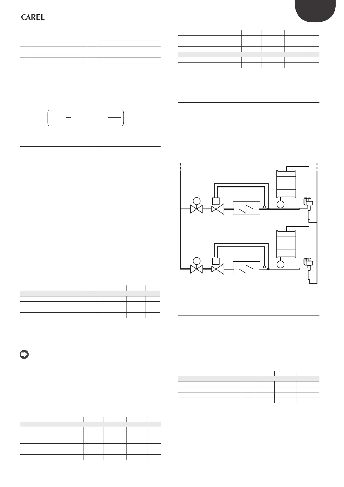
Special control5.3
EPR back-pressure
This type of control can be used in many applications in which a constant
pressure is required in the refrigerant circuit. For example, a refrigeration
system may include different showcases that operate at different
temperatures (showcases for frozen foods, meat or dairy). The different
temperatures of the circuits are achieved using pressure regulators
installed in series with each circuit. The special EPR function (Evaporator
Pressure Regulator) is used to set a pressure set point and the PID control
parameters required to achieve this.
S1
EVD
evolution
P
E
V1 V2
EV
M T
S1
EVD
evolution
P
E
V1 V2
EV
M T
Fig. 5.b
Key:
V1 Solenoid valve E Evaporator
V2 Thermostatic expasnion valve EV Electronic valve
For the wiring, see paragraph 2.7 “General connection diagram”.
This involves PID control without any protectors (LowSH, LOP, MOP,
HiTcond, see the chapter on Protectors), without any valve unblock
procedure and without auxiliary control. Control is performed on the
pressure sensor value read by input S1, compared to the set point: “EPR
pressure set point”. Control is direct, as the pressure increases, the valve
opens and vice-versa.
Parameter/description Def. Min. Max. UOM
CONTROL
EPR pressure set point 3,5 -20 (-290) 200 (2900) barg (psig)
PID: proportional gain 15 0 800 -
PID: integration time 150 0 1000 s
PID: derivative time 5 0 800 s
Tab. 5.e
 Loading...