12
ENG
“EVD evolution” +030222041 - rel. 1.0 - 01.06.2008
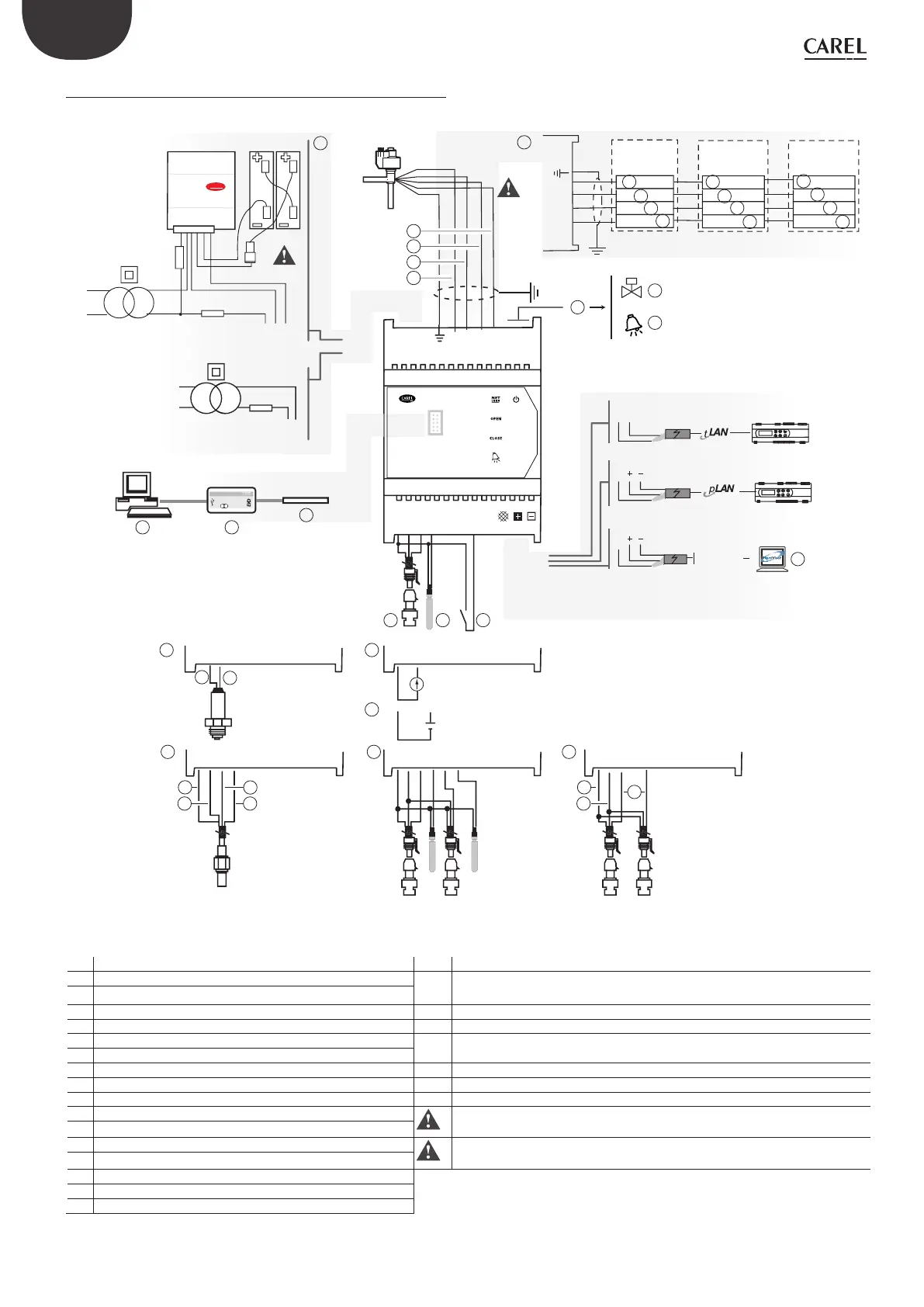
General connection diagram2.7
G
G0
G
G0
VBAT
COM1
NO1
1
3
2 4
Tx/Rx
GND
DI1
S4
S3
S2
S1
GND
DI2
VREF
Tx/Rx
GND
DI1
S4
S3
S2
S1
GND
DI2
VREF
2 AT
24 Vac
230 Vac
30VA
Power supply module
CAREL
24V
G0
GND
B+
B-
OUT
24 Vac
230 Vac
2AT
2AT
30VA
G
G0
VBAT
1
EVD
G
G0
VBAT
COM1
NO1
shield
shield
shield
shield
with batterywithout battery
1
3
2
4
Sporlan
SEI / SEH / SER
DANFOSS
ETS
ALCO
EX5/6
EX7/8
EVD4
PC
EVD4 service USB adapter
4
Tx/Rx
GND
pCO
GNDGND
RS485
Modbus®
pCO
S
1
1
1 1
2
3
3
4
4
4
1
4
5 6
7
8
A
B C
D
E F G
H
9 10
11
E
X
V
12
13
15
15 15
16
14 14
EVD0000E0*: tLAN version
EVD0000E1*: pLAN version
EVD0000E2*: RS485 version
2
Tx/Rx
GND
DI1
S4
S3
S2
S1
GND
DI2
VREF
Tx/Rx
GND
DI1
S4
S3
S2
S1
GND
DI2
VREF
4
15
17
14
1
Tx/Rx
GND
DI1
S4
S3
S2
S1
GND
DI2
VREF
Tx/Rx
GND
DI1
S4
S3
S2
S1
GND
DI2
VREF
1
15
3
EVD evolutio n
Fig. 2.j
Key:
1 white A Connection to EVBAT200/300
2 yellow B Connection to electronic pressure sensor (SPK**0000) or piezoresistive pressure
transducer (SPKT00**C0)
3 brown
4 green C Connection as positioner (4 to 20 mA input)
5 confi guration computer D Connection as positioner (0 to 10 Vdc input)
6 USB/tLAN converter E Connection to combined pressure/temperature sensor (SPKP00**T0)
7 adapter
8 ratiometric pressure transducer F Connection to backup sensors (S3, S4)
9 NTC sensor G Ratiometric pressure transducer connections (SPKT00**R0)
10 digital input 1 to enable control H Connections o other types of valves
11 free contact (up to 230 Vac)
1
The maximum length of the connection cable to the EVBAT200/300 module is 5 m.
12 solenoid valve
13 alarm signal
2
The connection cable to the valve motor must be 4-wire shielded, AWG 18/22
Lmax= 10 m
14 red
15 black
16 blue
17 supervision computer
 Loading...