ROUBLESHOOTING
669224-R5
T
12
4.1 General Procedures
4.1-1 Truck System Requirements
• Truckhydraulicpressureshouldbewithintherange
showninSpecications,Section6.1.PRESSURE TO
THE ATTACHMENT MUST NOT EXCEED 2300 psi
(160 bar).
• Hydraulicowshouldbewithintherangeshownin
Specications,Section6.1
• Hydraulicuidsuppliedtotheattachmentmustmeet
therequirementsshowninSpecications,Section6.1.
4.1-2 Tools Required
Inadditiontoanormalselectionofmechanic'shandtools,
thefollowingarerequired:
• In-LineFlowMeterKit:
10GPM(37L/min)–CascadePartNo.671476
OR
20GPM(75L/min)–CascadePartNo.671477
• PressureGaugeKit:
5000psi(345bar)–CascadePartNo.671212
• Assortedttings,hosesandquick-disconnectcouplers,
asrequired.
4.1-3 Troubleshooting Chart
WARNING: Beforeservicingany
hydrauliccomponent,relievepressurein
thesystem.Turnthetruckoffandmove
thetruckauxiliarycontrolvalvesseveral
timesinbothdirections.
Aftercompletinganyserviceprocedure,testthe
attachmentthroughseveralcycles.Firsttestthe
attachmentemptytobleedanyairtrappedinthe
systemtothetrucktank.Thentesttheattachment
withaloadtobesureitoperatescorrectlybefore
returningtothejob.
Stayclearoftheloadwhiletesting.Donotraisethe
loadmorethan4in.(10cm)offtheoorwhiletesting.
GA0013.eps
GA0014.eps
AC0127.eps
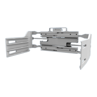
Flow Meter Kits: 671476 & 671477
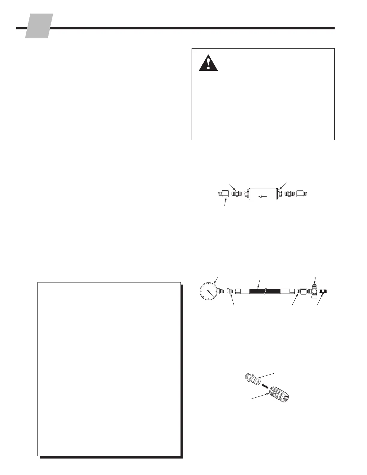
Pressure Gauge Kit: 671212
Quick-Disconnect Couplers
(2)No.8-12JIC/O-Ring
FlowMeter
(2)No.6-8JIC
Reducer
Pressure
Gauge*
No.6-6Hose*
No.6and
No.8JIC
SwivelTee
No.4-6Pip/JIC*
No.6-8JIC
Reducer
No.4,No.6*
andNo.8
JIC/O-Ring
*NOTE: DiagnosticsKit397382
includesitemsmarked.
MaleStraightThread
O-RingCoupler:
No.4(PartNo.212282)*
No.5(PartNo.210378)
No.6(PartNo.678592)
FemaleJICThread
Coupler:
No.4(PartNo.210385)*
No.6(PartNo.678591)
Determine All The Facts –Itisimportantthatall
thefactsregardingtheproblemaregatheredbefore
beginningserviceprocedures.Therststepisto
talktotheequipmentoperator.Askforacomplete
descriptionofthemalfunction.Thefollowing
guidelinescanthenbeusedasastartingpointto
begintroubleshootingprocedures:
Clamp Circuit
• Attachmentdropsloadafterithasbeenpickedup.
• Attachmentwillnotcarryloadtoitsratedcapacity.
• Attachmentarmshaveuneventravel.
• Attachmentarmstravelslowly.
• Attachmentarmswillnotmove.
Tocorrectoneoftheseproblems,seeSection4.4-1
and4.4-2.
Sideshift Circuit
• Attachmentdropsloadwhilesideshifting.
• Attachmentdropsloadatendofsideshiftstroke.
• Attachmentsideshiftsleftandrightatdifferent
speeds.
• Attachmentwillnotsideshift.
• Attachmentarmswillnotmove.
Tocorrectoneoftheseproblems,seeSection4.4-2,
4.4-3and4.4-4.
 Loading...