669224-R5
ERVICE
S
29
5.2-6 Turnafork Arm Service (Continued)
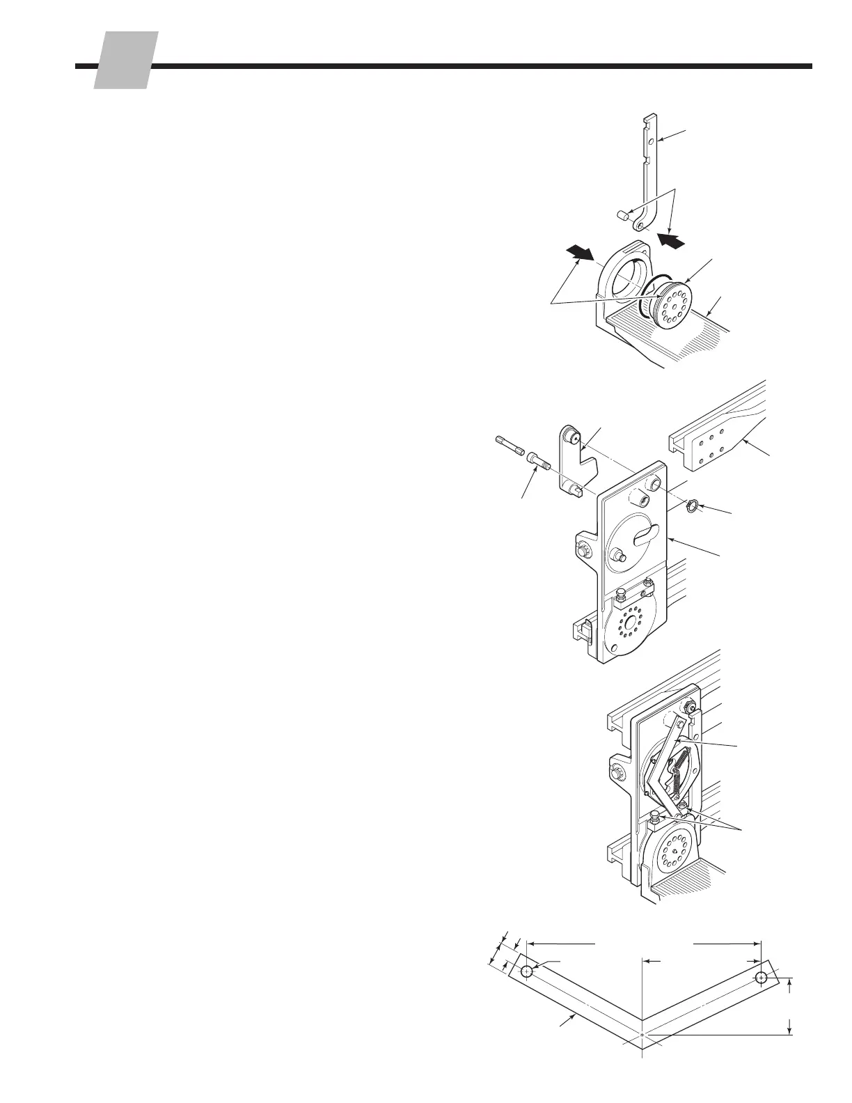
9 Remove the crank bar from the fork arm by driving out
the pivot pin from the front side of the fork arm.
10 Tap the bearing out of the fork arm from the back side
with a rubber mallet.
11 To remove the actuator, the upper arm bar must be
disassembled from the arm carrier. Remove the side
upper arm capscrews, as described in Section 5.2-2,
step 2. Slide the arm bar inward to gain access to the
actuator.
12 Remove the snap ring retaining the actuator to the arm
carrier, if equipped. Remove the actuator from the back
side of the arm carrier.
13 For reassembly, reverse the above procedures excepts
as follows:
• Inspect all components and bushings for wear.
Replace all worn components.
• Replace the fork arm bearing O-ring if damaged.
• Inspect the detent pin, spring, bushing and
wearplate. Replace all worn parts.
• Lubricate the fork arm bearing with chassis grease
prior to inserting into the fork arm.
• Use two of the bearing capscrews 180° apart as
guides to align the bearing/fork arm with the arm
carrier mounting holes during reassembly.
• Make sure the arm turns freely on the bearing after
tightening the capscrews.
• Lubricate all zerk fittings with chassis grease.
• On early style arms without a snap ring retaining
on bell crank, the fabricated bar shown below must
be installed. This bar allows the arms to be indexed
with the covers off to adjust the horizontal and
vertical stops.
• The two capscrew stops should be adjusted so the
arm stops at a true horizontal and vertical position
when it is indexed. In the vertical (clamp) position,
the capscrew should stop the arm so it just engages
the detent pin in the arm base. Tighten the nuts to
80–90 ft.-lbs. (110–122 Nm).
CL4407.eps
9
10
Crank Bar
Fork Arm Bearing
Fork Arm
CL4408.eps
Actuator
Upper
Arm Bar
Arm Carrier
12
11
CL4409.eps
Make a bar
to secure the
uncovered
mechanism
Capscrew
Stops
5.2-7 Turnafork Arm Indexing
Fully closing the arms depresses the actuators. This
releases the locking mechanism and causes the arms to
rotate. If the arms get out of phase (one or both arms not
horizontal or vertical), correct the problem as follows:
IMPORTANT: If the arms ever get out of phase, there may
be nothing mechanically wrong with the attachment. This
condition usually occurs when the actuators are not fully
depressed.
To reposition an arm manually: With the arms fully closed
(actuators fully depressed), reposition one arm by hand.
To reposition an arm hydraulically: Close the arms
hydraulically (actuators fully depressed). Then open the
arm slowly until you hear one click. Immediately close the
arms together again to bring them back in phase.
CL0343.eps
3.75 in.
(9.5 cm)
1.50 in. (38 mm)
.75 in. (19 mm)
MATERIAL:
.25 in. (7 mm)
Steel Plate
14.25 in. (36.2 cm)
7.12 in. (18.1 cm)
.75 in. (19 mm)
DIA. - 2 places
 Loading...