EasyManua.ls Logo

Cascade 35D User Manual

Default Icon
46 pages
To Next Page IconTo Next Page
To Previous Page IconTo Previous Page
Page #39 background image
669224-R5
ERVICE
S
37
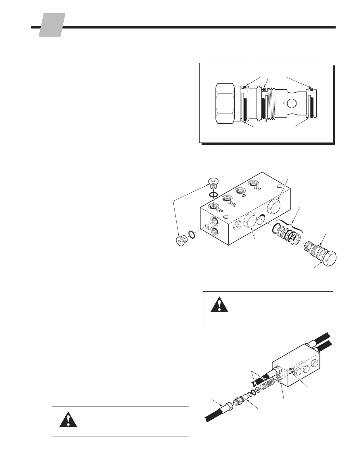
5.6-4 Check Valve Service –
Center Mount Valves
IMPORTANT: Service the check valve in a clean work
area.
1 Remove the cartridge valves. The non-sideshifting
check valve has one cartridge valve, the sideshift check
valve has three cartridge valves.
2 Remove all plugs and fittings.
3 Remove the O-rings and back-up rings from the
cartridge valve, fittings and plugs.
4 Clean all parts with cleaning solvent.
6 For reassembly, reverse the above procedures except
as follows:
• The cartridge valve back-up rings and O-rings must
be installed as shown to avoid seal damage during
reassembly.
• Lubricate cartridges and seals with petroleum jelly
prior to reassembly.
5.6-5 Eliminating the Arm Opening
Regenerative Function
The 25D, 35D, 40D and 50D attachments utilize a
regenerative hydraulic circuit in the arm opening mode.
The arms open at a faster speed than when closing. The
regenerative circuit can be eliminated (use Service Kit
212867) to give equal arm speed when opening and
closing the arms as follows:
1 Open the attachment arms to the width of the frame.
2 Remove the hose from the check valve port marked CL.
3 Remove the special fitting from the CL port.
NOTE: The spool must remain in the CL port.
4 Install the spring and spacer supplied with the kit into
the CL port, as shown.
5 Reinstall the special fitting and hose.
NOTE: Operate the attachment through several cycles to
remove trapped air in the system and to check for proper
operation. Check for leaks.
CL1012.eps
O-Ring
Back-Up Ring
CL4423.eps
2
3
1
Sideshift Right
Cartridge Valve
Clamp Cartridge
Valve
Sideshift Left
Cartridge Valve
WARNING: Before removing any hoses,
relieve pressure in the hydraulic system.
Turn the truck off, then open the truck
auxiliary control valve(s) several times in
both directions.
WARNING: Make sure that the special
fitting is always installed in the CL port.
The attachment's arms will not function
properly without the special fitting installed.
OP
CL
CL4424.eps
2
3
4
Special Fitting
Spacer, Spring
CL Port
Spool (Do Not
Remove)

Table of Contents

Questions and Answers:

Cascade 35D Specifications

General IconGeneral
BrandCascade
Model35D
CategoryPower Tool
LanguageEnglish

Summary

INTRODUCTION

1.1 Introduction

Overview of the manual's scope and content.

1.2 Special Definitions

Explains WARNING, CAUTION, IMPORTANT, and NOTE statements.

INSTALLATION

2.1 Truck Requirements

Details truck specifications for attachment compatibility.

2.2 Recommended Hydraulic Supply

Specifies hose and fitting requirements for hydraulic supply.

2.3 Installation Procedure

Step-by-step guide for attaching the unit to the truck.

2.4 Custom Arm Installation

Guide for installing custom arms onto the base.

2.5 Prior to Operation

Pre-operation checks and adjustments for the attachment.

PERIODIC MAINTENANCE

3.1 100-Hour Maintenance

Routine checks and tasks every 100 operating hours.

3.2 500-Hour Maintenance

Tasks to perform every 500 operating hours.

3.3 1000-Hour Maintenance

Tasks to perform every 1000 operating hours.

3.4 2000-Hour Maintenance

Tasks to perform every 2000 operating hours.

TROUBLESHOOTING

4.1 General Procedures

General advice and requirements for troubleshooting.

4.2 Plumbing – Top Mount Valve

Hosing diagrams and circuit schematics for top mount valves.

4.2-3 Hosing Diagram, Sideshifting (including Turnafork)

Hosing diagrams for sideshifting attachments.

4.3 Plumbing – Center Mount Valve

Hosing diagrams and schematics for center mount valves.

4.4 Attachment Troubleshooting

Identifies common issues affecting clamp function.

4.4 Electrical Circuit (Solenoid Equipped Attachments)

Troubleshooting steps for electrical circuits.

SERVICE

5.1 Attachment Removal

Step-by-step guide to safely remove the attachment.

5.2 Arms

Procedures for arm assembly removal and installation.

5.3 Cylinders

Procedures for cylinder removal and installation.

5.4 Cylinder Service

Procedures for cylinder disassembly and inspection.

5.5 Restrictor Cartridges

How to adjust and service restrictor cartridges.

5.6 Check Valves

Procedures for removing and servicing check valves.

5.7 Base Unit

Procedures for disassembling and reassembling the base unit.

5.8 Solenoid Valve

Procedures for solenoid valve coil and valve service.

SPECIFICATIONS

6.1-1 Hydraulics

Details hydraulic settings, flow volumes, and fluid requirements.

6.1-2 Auxiliary Valve Functions

Lists auxiliary valve functions and their compliance with ITA standards.

6.1-3 Truck Carriage

Details carriage mount dimensions for ITA compatibility.

6.1-4 Torque Values

Lists torque values for various fasteners in US and metric units.

Related product manuals