669224-R5
ERVICE
S
25
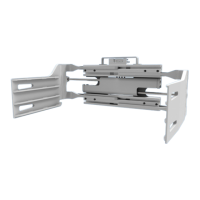
5.2-2 Bolt-On Arm Removal
The following procedures can be performed with the
attachment on the truck and with the arm assemblies on
the attachment. If the arm assemblies have been removed
(Section 5.2-1), lay the arm assembly down with the arm
back on the ground.
1 Extend the arms outside the width of the frame.
Remove the cotter pin, locking cap and nut retaining the
cylinder rod to the arm lug.
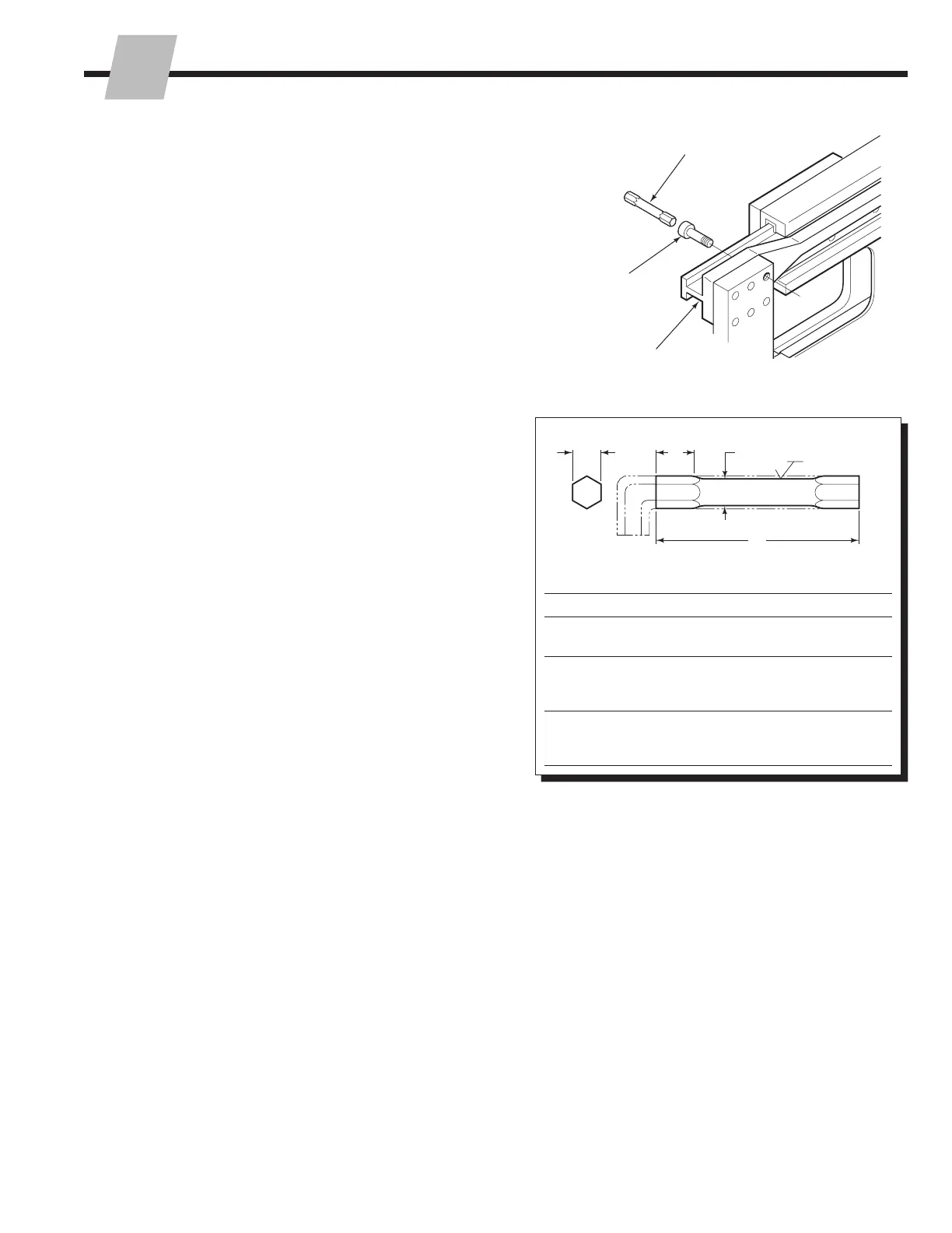
2 Remove the arm capscrews using drive extension
tool part no. 668020 (25D), 6676699 (35D, 40D, 50D)
or 676215 (70D, 80D, 100D). A torque multiplier is
required to remove and tighten the 70D, 80D, 100D
capscrews.
Short drive adapters are commercially available:
Williams .50 in. drive to .625 in. hex (25D) and .50
in. drive to .625 in. hex (35D, 40D, 50D) and .75 in.
drive to .75 in. hex (70D, 80D, 100D). Drive extension
dimensions are provided to make the tool from the allen
wrench. Do not use mild steel hex stock.
IMPORTANT: Be careful not to damage the arm bar.
Premature bearing failure will occur.
3 For reassembly, reverse the above procedures, except
for the following instructions:
• Tighten the capscrews (lubed) to the torque values
below. Arms should be free to slide in the frame
manually. If necessary, realign and retorque the
capscrews.
25D – 190–220 ft.-lbs. (257–298 Nm)
35D, 40D, 50D – 280–320 ft.-lbs. (380-434 Nm)
70D, 80D, 100D – 680–720 ft.-lbs. (922-976 Nm)
IMPORTANT: Be careful not to damage the arm bar.
Premature bearing failure will occur.
• Install the cylinder anchor nuts as described in
Section 5.2-1, Step 6.
IMPORTANT: Capscrews must be torqued to the values
shown above. If lost or broken, replace only with similar
GRADE 8 (ISO property class 10.9) hex socket head
capscrews.
CL0455.eps
Drive
Extension
2,3
Arm Bar
CL0456.eps
A
Hex
B
C
D
63
Dimensions – in. (mm)
Model A B C D
25D
.50
(12.7)
.75
(19.0)
.46
(11.6)
3.50
(88.0)
35D
40D
50D
.62
(15.7)
.50
(12.7)
.58
(14.7)
3.50
(88.0)
70D
80D
100D
.75
(19.0)
.50
(12.7)
.75
(19.0)
5.00
(127.0)
 Loading...