669224-R5
ERVICE
S
31
5.3-1 Cylinder Removal and
Installation (Continued)
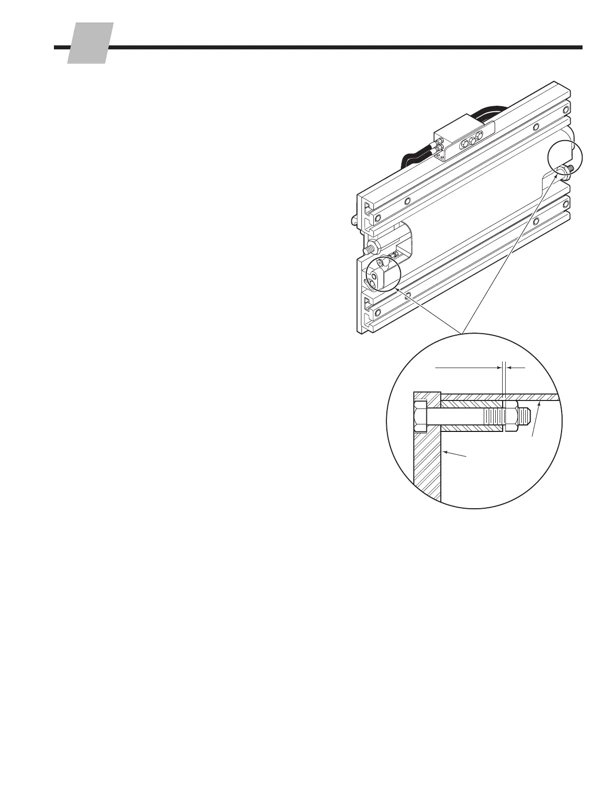
9 For reassembly, reverse the above procedures except
for the following special instructions for the cylinder
anchor nuts and the bumper:
• Install the bumper. Tighten the self-locking nuts
to leave .050–.080 in. (1.3–2.0 mm) end play for
each capscrew. This clearance allows for cylinder
alignment during clamping without overstressing the
capscrews.
• Lubricate the cylinder rod threads, but threads and
spherical portion of nut with wheel bearing grease.
• Install the washer on the rod end with the beveled
side facing the lug.
• Engage the rod end into the lug.
• Tighten the rod end nut to a torque values below.
Prevent the rod from turning by using a wrench on
the hex washer.
25D, 35D, 40D, 50D – 150–175 ft.-lbs. (200–235 Nm)
70D, 80D, 100D – 225–250 ft.-lbs. (305–340 Nm)
NOTE: The rod end nut is being tightened against
the hex washer. The nut will not be tight against the
arm lug. This looseness allows for cylinder alignment
during clamping.
• Install the locking cap and cotter pin.
• Lubricate the bearing portion of the arm bars with a
thin film of chassis grease.
• Operate the attachment through several full cycles
to force air in the system to the truck hydraulic tank.
Check for leaks.
CL4413.eps
.05 in. (1.3 mm)
.08 in. (2.0 mm)
Bumper
Lug
 Loading...