2-10 Installation
5150 Service Aggregation Switch Hardware Installation and Start-up Manual
009-3222-001 Standard Revision H
Copyright
©
2012-2015 Ciena
®
Corporation July 2015
Transceivers
The faceplate of the 5150 has:
• 48 connections which use 100/1000 Mbps Ethernet pluggable SFPs.
Copper SFPs installed in these ports support 10/100/1000 Mbps.
• up to 4 connections which use 10 Gigabit Ethernet pluggable XFPs.
Figure 1-1 on page 1-2 shows the location of these different ports on the
faceplate of the 5150. For more information about the ports see 39XX/51XX
Product Fundamentals.
The SFP/XFP modules provide the media-specific portion of an interface,
allowing it to support Ethernet using different media types. One optic module
can be installed into each available port and can be hot swapped.
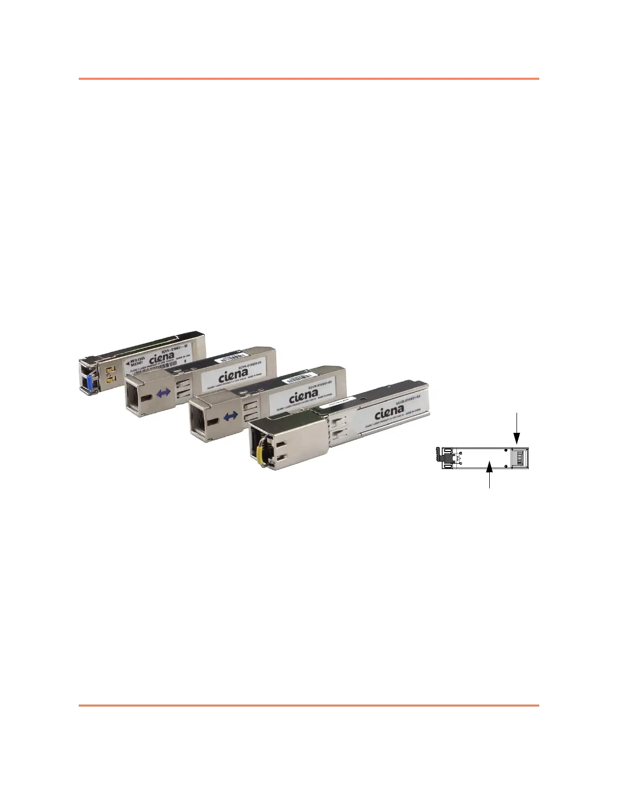
Figure 2-1 shows a typical pluggable optic module and its parts.
Figure 2-1
Pluggable Optic Modules
The installation procedure is the same for both SFP and XFP optics. However,
ensure that the installed optic matches the capability of the port and that the
optic is supported by the system. The list of supported XFPs and SFPs is
documented in Packet Networking Transceivers Reference (009-2011-602).
Unsupported optics will generate an LED indication and will not function. See
“LED Overview” on page 5-1 for more information.
For additional information see:
• “To Install a Pluggable Optic” on page 2-27
• “To Remove a Pluggable Optic” on page 2-28
20-pin connector
Bottom of module
 Loading...

