Installation 2-23
5150 Service Aggregation Switch Hardware Installation and Start-up Manual
009-3222-001 Standard Revision H
Copyright
©
2012-2015 Ciena
®
Corporation July 2015
3 Using a Phillips screwdriver, secure the modules in place using the captive
hold down screw on the right of the module.
4 Prepare the DC power cord. The power cord should be a minimum 14 gauge
wire and should be of a length suitable for your installation. Remember to
allow the necessary slack for the cable to be properly retained between the
chassis and the terminal block. You will also need to install fork terminal
spade lugs suitable for the installation environment on the wires. Use UL/CSA
approved parts and local practices to install spade lugs at both the chassis
and terminal block ends of the power cord.
Note: Table 2-2 on page 2-9 provides a summary of the DC lugs that are
recommended for use with the 5150.
Note: After it is installed, the power cord will be dressed to the right,
across the front of the power supply. It is not appropriate to dress the
power cord to the left, across the front of the 5150 chassis.
5 Remove power from the DC circuit(s) that will supply power to the system.
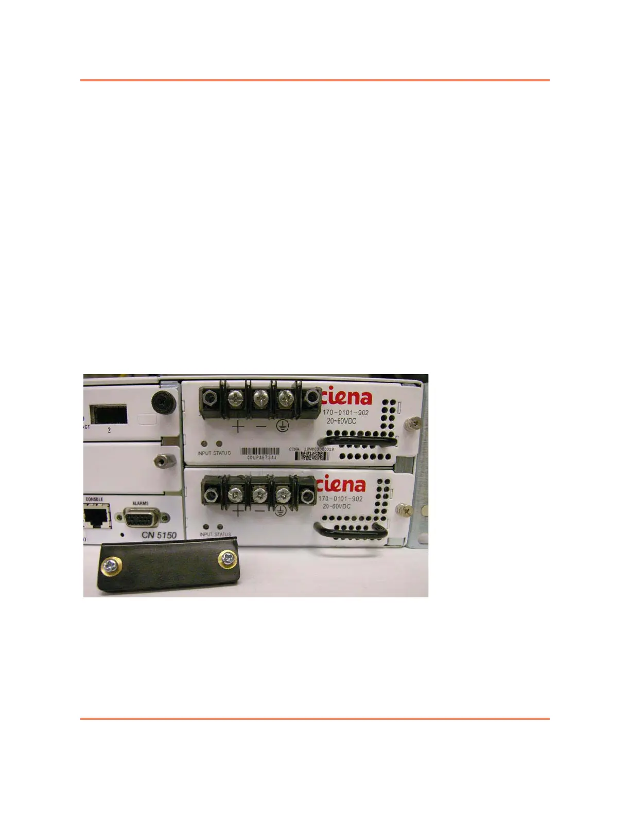
6 Using a Phillips screwdriver, remove the plastic terminal block cover from the
front of both power supplies and set them aside. See Figure 2-7.
Figure 2-7
Power Supply (with cover removed from modules)
 Loading...

