Mounting Options 8-3
5150 Service Aggregation Switch Hardware Installation and Start-up Manual
009-3222-001 Standard Revision H
Copyright
©
2012-2015 Ciena
®
Corporation July 2015
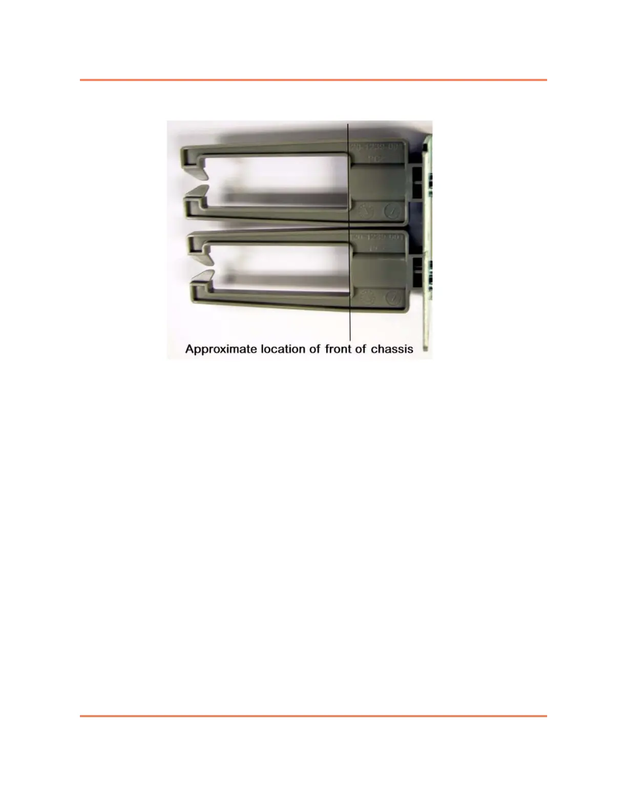
Figure 8-1
Bracket cable support, mounting offset shown
Note: The bracket will be installed on the sides of the chassis and near
the front of the chassis. The bracket will be positioned slightly behind the
front of the chassis. It is not installed flush with the front of the chassis.
When correctly installed, the back of the channel on the cable support
bracket will be approximately flush with the front of the chassis. See
Figure 8-1.
Four screws are used to attach each bracket to the side of the 5150 chassis.
The bracket has four holes available to attach to the mounting frame.
For a procedure see “Installing the 19” Frame Mount Bracket - 2 RU” on page
8-7.
 Loading...

