B-9
Catalyst 3750 Switch Hardware Installation Guide
OL-6336-10
Appendix B Connector and Cable Specifications
Cable and Adapter Specifications
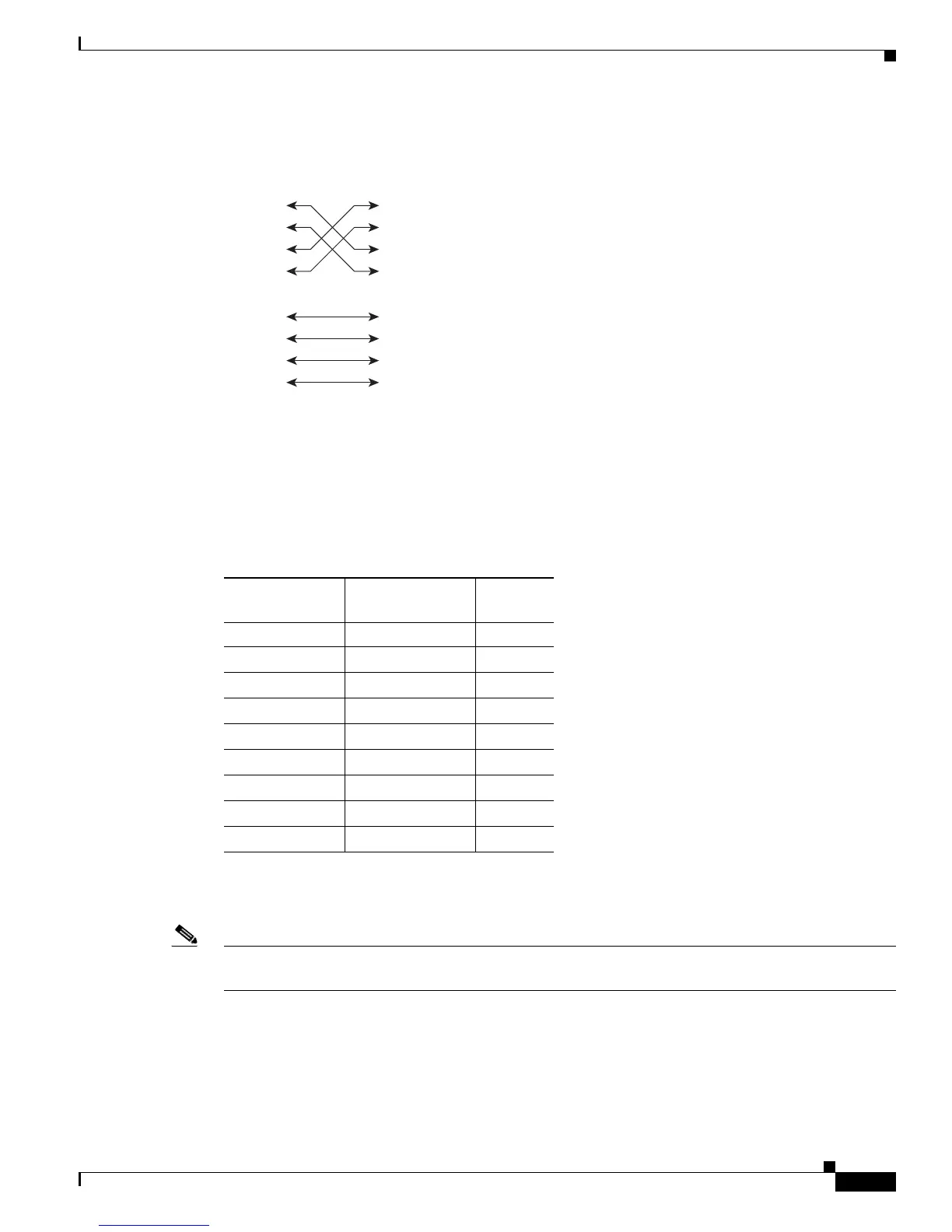
Figure B-13 Four Twisted-Pair Crossover Cable Schematics for 10/100/1000 and 1000BASE-T SFP
Module Ports
Crossover Cable and Adapter Pinouts
This section describes the adapter pinouts.
Table B-4 lists the pinouts for the console port, the RJ-45-to-DB-9 adapter cable, and the console device.
Table B-5 lists the pinouts for the console port, RJ-45-to-DB-25 female DTE adapter, and the
console device.
Note The RJ-45-to-DB-25 female DTE adapter is not supplied with the switch. You can order a kit (part number
ACS-DSBUASYN=) containing this adapter from Cisco.
1 TP0+
2 TP0-
3 TP1+
6 TP1-
1 TP0+
Switch Switch
2 TP0-
3 TP1+
6 TP1-
4 TP2+
5 TP2-
7 TP3+
8 TP3-
4 TP2+
5 TP2-
7 TP3+
8 TP3-
65274
Table B-4 Console Port Signaling Using a DB-9 Adapter
Switch Console
Port (DTE)
RJ-45-to-DB-9
Terminal Adapter
Console
Device
Signal DB-9 Pin Signal
RTS 8 CTS
DTR 6 DSR
TxD 2 RxD
GND 5 GND
GND 5 GND
RxD 3 TxD
DSR 4 DTR
CTS 7 RTS
 Loading...