1-6
Catalyst 3750 Switch Hardware Installation Guide
OL-6336-10
Chapter 1 Product Overview
Front Panel Description
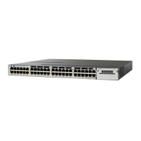
Catalyst 3750-48PS and 3750V2-48PS Switch Front Panel
The 10/100 PoE ports on the switch are grouped in pairs. The first member of the pair (port 1) is above
the second member (port 2), as shown in Figure 1-6. Port 3 is above port 4, and so on. The SFP module
slots are numbered 1 to 4.
Figure 1-6 Catalyst 3750-48PS and 3750V248-PS Switch
Gigabit Ethernet Switches
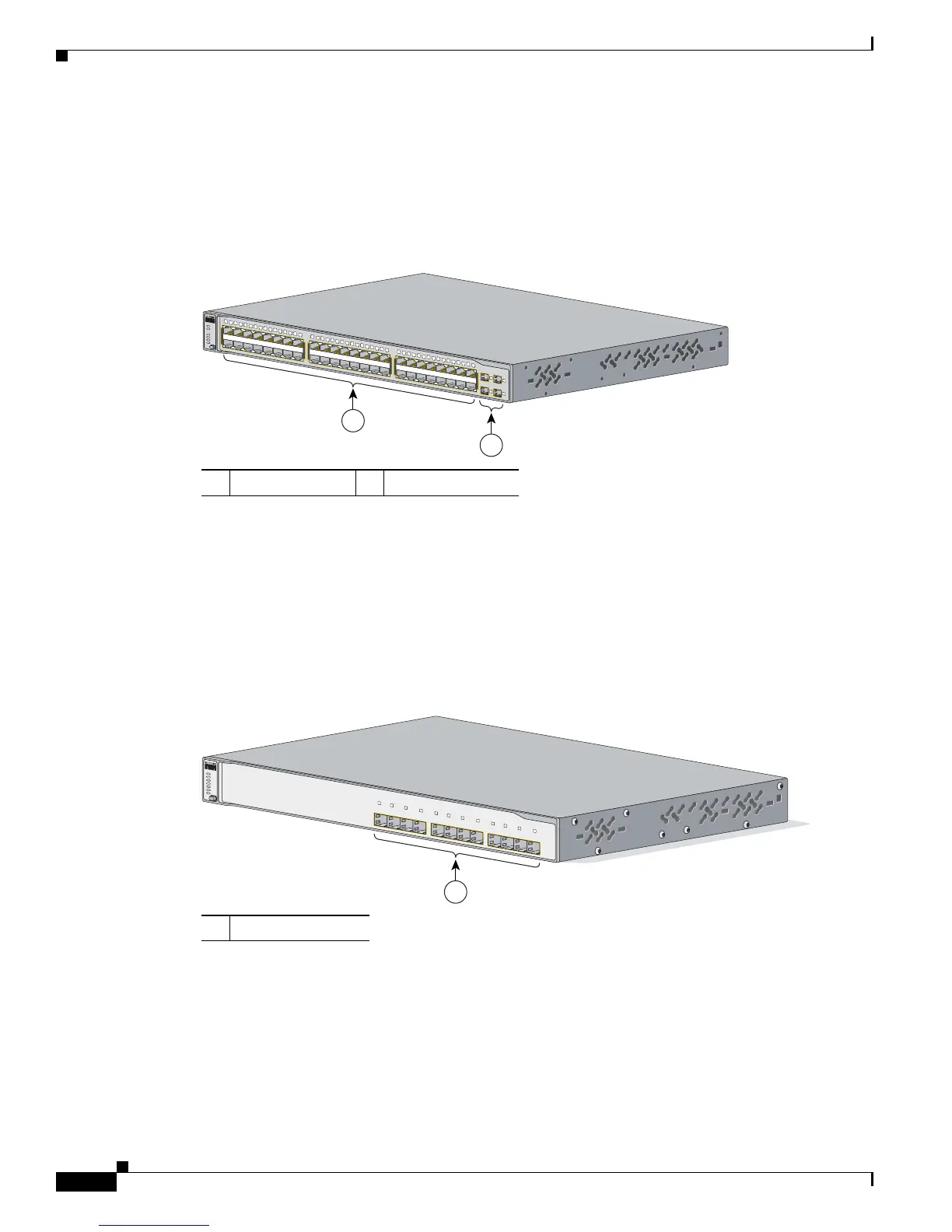
Catalyst 3750G-12S and Catalyst 3750G-12S-SD Switch Front Panel
The SFP module slots on the switch are numbered 1 through 12. The slots are grouped in three sets of
four, as shown in Figure 1-7.
Figure 1-7 Catalyst 3750G-12S and 3750G-12S-SD Switch
Catalyst 3750-24T, 3750G-24TS, and 3750G-24TS-1U Switch Front Panel
The 10/100/1000 ports on switch are grouped in pairs. The first member of the pair (port 1) is above the
second member (port 2), as shown in Figure 1-8, Figure 1-9, and Figure 1-10. Port 3 is above port 4, and
so on.
The SFP module slots are numbered 25 to 28 on the Catalyst 3750G-24TS Switch (Figure 1-9) and on
the Catalyst 3750G-24TS-1U Switch (Figure 1-10).
1 10/100 PoE ports 2 SFP module slots
104576
2
1
Catalyst 37
50
SERIES
SYST
RPS
STAT
DUPLX
SPEED
PoE
MODE
1
2
5
6
7
8
9
10
11
12
13
14
15
16
3
4
1X
2X
15X
16X
17
18
21
22
23
24
25
26
27
28
29 30
31
32
19
20
17X
18X
31X
32X
33
34
37
38
39
40
41
42
43
44
45 46
47
48
35
36
33X
34X
47X
48X
1
2
3
4
1 SFP module slots
Catalyst 3750
SERIES
SYST
RPS
MASTR
STAT
DUPLX
SPEED
STACK
MODE
4
1
2
3
12
9
10
11
8
5
6
7
1
97166
 Loading...