1-4
Catalyst 3750 Switch Hardware Installation Guide
OL-6336-10
Chapter 1 Product Overview
Front Panel Description
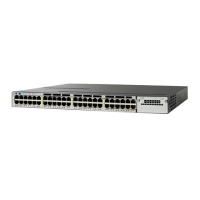
The downlink SFP module slots on the Catalyst 3750V2-24FS switch are numbered 1 through 24.
The slots are grouped in pairs. The first member of the pair (slots 1) is above the second member
(slots 2), as shown in Figure 1-2.
Note The Catalyst 3750V2-24FS switch supports the 100BASE-FX multimode fiber (MMF) SFPs only in the
downlink SFP module slots.
The uplink SFP modules slots are numbered 1 (left) and 2 (right).
Figure 1-2 Catalyst 3750V2-24FS Switch
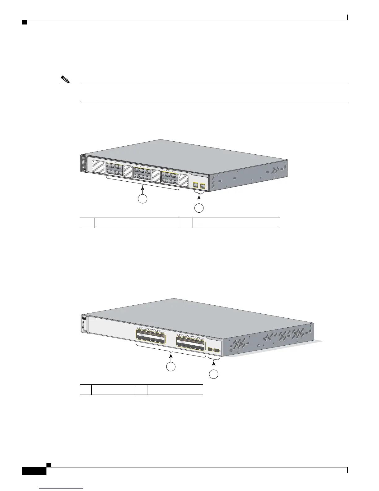
Catalyst 3750-24TS and 3750V2-24TS Switch Front Panel
The 10/100 ports on the switch are numbered 1 through 24. The ports are grouped in pairs. The first
member of the pair (port 1) is above the second member (port 2), as shown in Figure 1-3. Port 3 is above
port 4, and so on. The SFP module slots are numbered 1 (left) and 2 (right).
Figure 1-3 Catalyst 3750-24TS and 3750V2-24TS Switch
1 SFP module slots (downlink) 2 SFP module slots (uplink)
279984
1
2
1 10/100 ports 2 SFP module slots
Catalyst 3750
SERIES
SYST
RPS
MASTR
STAT
DUPLX
SPEED
STACK
MODE
13X
14X
23X
24X
1X
2X
11X
12X
1
2
1
2
3
4
5
6
7
8
9
10
11
12
13
14
15
16
17
18
19
20
21
22
23
24
2
1
86541
 Loading...