2-38
Catalyst 3750 Switch Hardware Installation Guide
OL-6336-10
Chapter 2 Switch Installation
Installing and Removing XENPAK Modules (Catalyst 3750G-16TD Switch)
Removing a XENPAK Module
To remove a XENPAK module, follow these steps:
Step 1 Attach an ESD-preventive wrist strap to your wrist and to a bare metal surface on the chassis.
Step 2 Disconnect the cable from the XENPAK module. For fiber-optic modules, install the optical bore dust
plugs.
Step 3 Loosen the two captive installation screws that secure the XENPAK module in the slot.
Step 4 Carefully pull on the two captive installation screws to disconnect the XENPAK module from the slot.
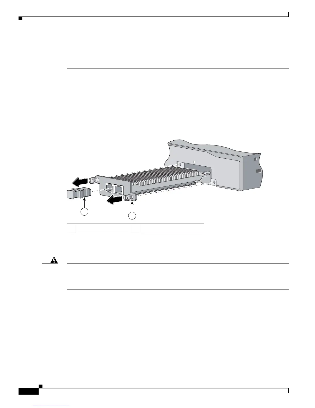
Step 5 Grasp the edges of the XENPAK module, and carefully slide it out of the slot, as shown in Figure 2-53.
Figure 2-53 Removing a XENPAK Module
Step 6
Use two Phillips-head screws to attach the XENPAK module slot cover to the switch front panel, as
shown in Figure 2-54.
Warning
Blank faceplates (filler panels) serve three important functions: they prevent exposure to hazardous
voltages and currents inside the chassis; they contain electromagnetic interference (EMI) that might
disrupt other equipment; and they direct the flow of cooling air through the chassis. Do not operate
the system unless all cards and faceplates are in place.
Statement 156
1 Optical bore dust plug 2 Captive installation screw
Catalyst 3750
series
104574
2
1
TX
RX
1
 Loading...