Chapter 6 Connecting Interface Cables on the ASA 5500, ASA 5510, ASA 5520, and ASA 5540 Platforms
Connecting to a 4GE SSM
6-6
Cisco ASA 5500 Series Getting Started Guide
78-19186-01
Note You can use any unused Ethernet interface on the device as the failover
link. The failover link interface is not configured as a normal networking
interface; it should only be used for the failover link. You can connect the
LAN-based failover link by using a dedicated switch with no hosts or
routers on the link or by using a crossover Ethernet cable to link the units
directly. For more information, see the Configuring Failover chapter in
the Cisco ASA 5500 Series Configuration Guide using the CLI. See also
Chapter 4, “Ports and LEDs”for information about the Ethernet
interfaces.
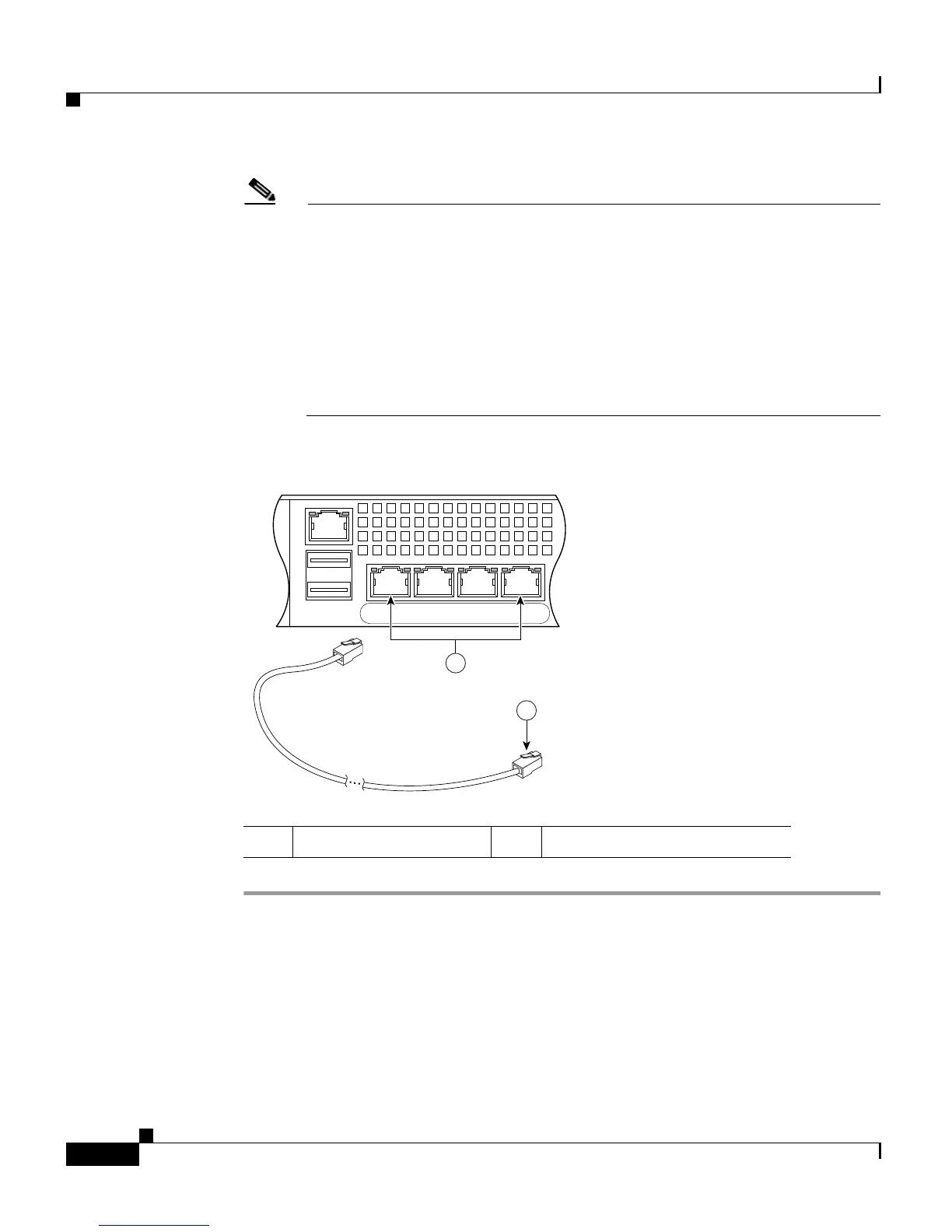
Figure 6-4 Connecting Cables to Network Interfaces
Connecting to a 4GE SSM
The 4GE SSM is optional; therefore, this step is necessary only if you have
installed a 4GE SSM on the adaptive security appliance.
1 RJ-45 Ethernet ports 2 RJ-45 connector
USB2
USB1
LNK SPD
3
LNK SPD
2
LNK SPD
1
LNK SPD
0
MGMT
92685
2
1
 Loading...