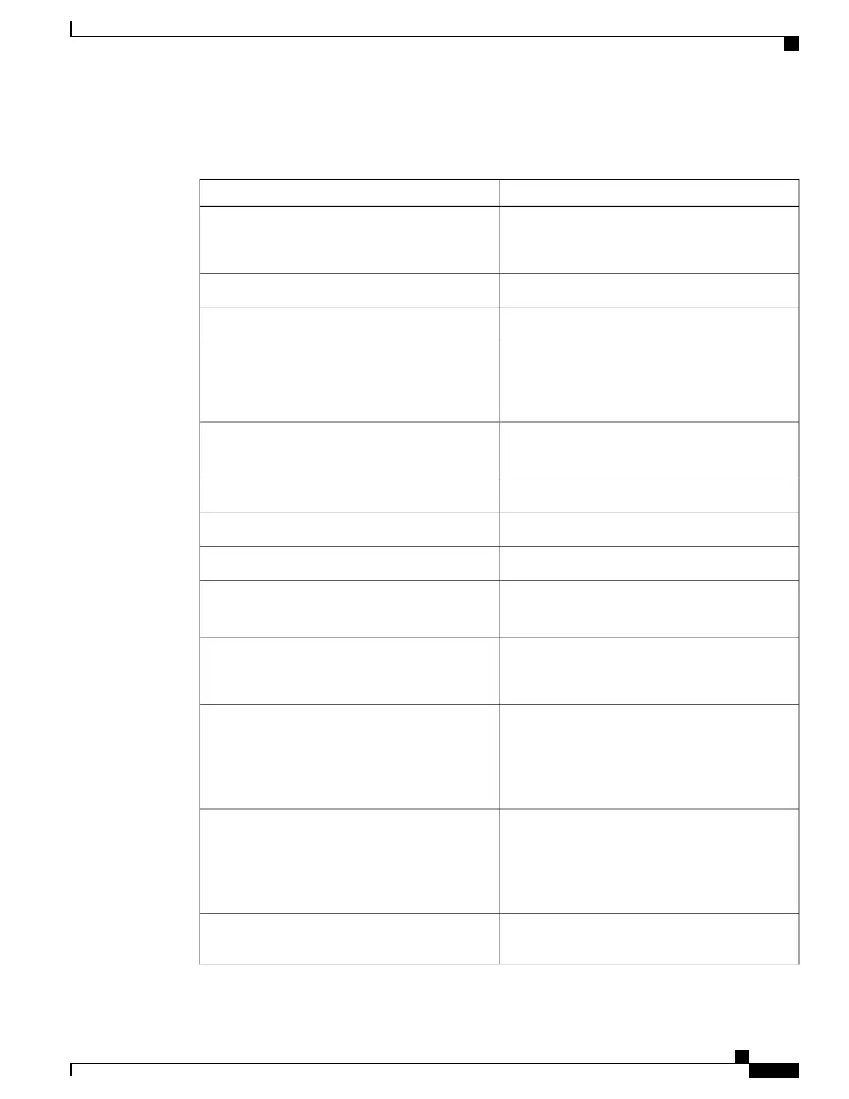
The following table shows each field and its description.
Table 3: Field Description
DescriptionField
Shows that the SONET controller is operating. The
controller's state can be up, down, or administratively
down.
SONET 0/3/3 is up
Shows the rate configured on the port.Port configured rate: OC3
Shows the section level alarm counters.SECTION: LOS = 0 LOF = 0 BIP = 0
Shows the PMON for the port.SONET Section Tables:
INTERVAL CV ES SES SEFS
05:50-05:58 0 0 0 0
Shows the line level alarm counters.LINE:
AIS = 0 RDI = 0 REI = 0 BIP(B2) = 0
Shows the active alarms on the port.Asserted/Active Alarms: None
Shows BER thresholds.BER thresholds: SF = 10e-3 SD = 10e-6
Shows the K1 and K2 values.K1 = 00, K2 = 00
Shows the path level clock.PATH 1:
Clock Source is internal
Shows the path layer alarm counters.AIS = 0 RDI = 0 REI = 0 BIP(B3) = 0 LOP = 0 PSE
= 0 NSE = 0 NEWPTR = 0 LOM = 0 PLM = 0 UNEQ
= 0
Shows the alarms on the path.Active Defects: None
Detected Alarms: None
Asserted/Active Alarms: None
Alarm reporting enabled for: PLOP LOM B3-TCA
shows the Rx and Tx C2 bytes.TCA threshold: B3 = 10e-6
Rx: C2 = 00 =====> rx and tx C2 byte..
Tx: C2 = 02
PATH TRACE BUFFER : UNSTABLE
Shows the path trace.00 00 00 00 00 00 00 00 00 00 00 00 00 00 00 00
…………….
1-Port OC-192 or 8-Port Low Rate CEM Interface Module Configuration Guide, Cisco IOS XE Everest 16.7.x (Cisco
ASR 900 Series)
47
Configuring SONET
Managing and Monitoring SONET Line

 Loading...


