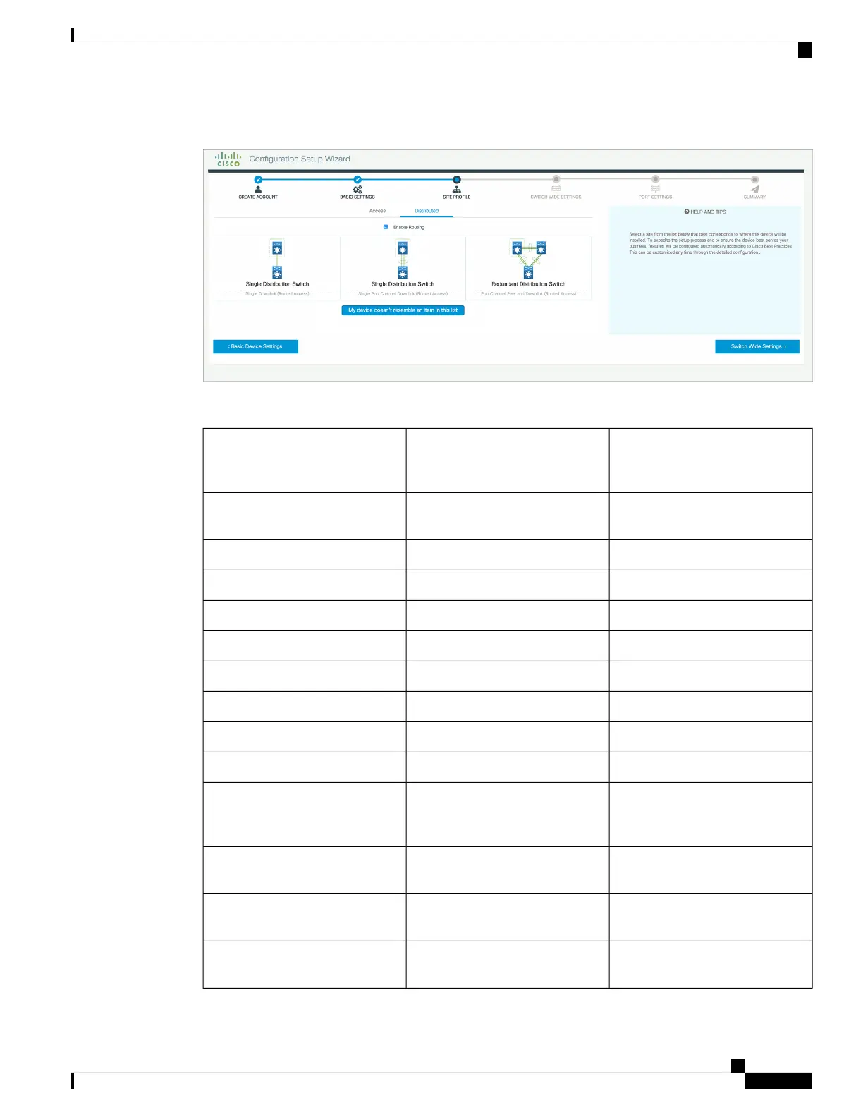
Figure 70: Site Profile - Distribution Switches (with Routed Access)
Table 25: Default Configuration Loaded with Each Site Profile (Core Switches)
Standalone Collapsed Core Switch
(with ECMP Peer and Port Channel
Downlink)
Standalone Core Switch (with
ECMP Peers)
Setting
The hostname or device name you
provided as part of Quick Setup
The hostname or device name you
provided as part of Quick Setup
Hostname
EnabledEnabledUDLD
Recovery mode set to AutoRecovery mode set to AutoError Disable Recovery
Source Destination IPSource Destination IPPort Channel Load Balance
Version 2Version 2SSH
EnabledEnabledSCP
EnabledEnabledVTY Access to Switch
Unicast RPF (uRPF) in strict modeUnicast RPF (uRPF) in strict modeMitigate Address Spoofing
EnabledEnabledService Timestamp
Layer 3 settings configured on the
management port, based on Quick
Setup
Layer 3 settings configured on the
management port, based on Quick
Setup
Management Interface
QoS Policy for Distribution/Core
defined
QoS Policy for Distribution/Core
defined
QoS Policy
Selected uplink ports connect to
MAN/WAN device
Selected uplink ports connect to
MAN/WAN device
Uplink Interfaces
Downlink connections to
distribution switches
Downlink connections to access
switches
Downlink Interfaces
Cisco Catalyst 9400 Series Switches Hardware Installation Guide
147
Initial Configuration for the Switch
Configuring Your Device Based on a Site Profile
 Loading...