Before you begin
To check the operation of the fans, you should have powered up the chassis.
Procedure
Step 1 Listen for the fans; you should immediately hear them operating. If you do not hear them, ensure
a) That the fan tray is inserted completely in the chassis
b) That the faceplate is flush with the chassis panel.
c) That the captive installation screws have been tightened sufficiently.
If the fan tray is not installed correctly, the fans may not run at all, or they may run at full speed.
When the fan tray operates at full speed, increased noise levels may be expected.
Important
Step 2 Check if the fan tray LED is lit and is green.
Step 3 If after several attempts the fans do not operate, or if you experience trouble with the installation (for instance,
if the captive installation screws do not align with the chassis holes), contact the Cisco TAC for assistance.
Removing and Installing the Power Supply
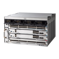
Cisco Catalyst 9400 Series chassis support one to eight field-replaceable, AC-input power supply modules,
each with its own on/ off rocker switch.
This section describes how to remove and install the AC-input power supplies for the chassis.
The power supplies are hot-swappable, so in redundant mode, you do not have to power down the switch to
replace or upgrade the power supplies.
Installing the Power Supply
Before you begin
Ensure that you have installed the cable guide before you begin the procedure. This is to properly guide and
arrange the power cords that you will attach as part of the installation. Since there are two rows of power
supply bays, the cable guide ensures that the power cords from one row of power supplies do not interfere
with the removal or replacement of modules in another row.
Procedure
Step 1 Remove the replacement power supply from its shipping packaging.
Step 2 Verify that the replacement power supply power switch is in the off (0) position.
Step 3 If installed, remove the blank power supply cover from the empty power supply bay. For information about
removing blank covers, see Removing and Installing Power Supply Blanks, on page 96. Save the blank cover
for future use.
Cisco Catalyst 9400 Series Switches Hardware Installation Guide
89
Removing and Replacing FRUs
Removing and Installing the Power Supply
 Loading...
