• Grounding wire—The grounding wire should be sized according to local and national installation
requirements. Depending on the power supply and system, a 12 to 6 AWG copper conductor is required
for U.S. installations. Commercially available 6-AWG wire is recommended. The length of the grounding
wire depends on the proximity of the switch to proper grounding facilities.
• No. 1 Phillips screwdriver.
• Crimping tool to crimp the grounding wire to the grounding lug.
• Wire-stripping tool to remove the insulation from the grounding wire.
Procedure
Step 1 Use a wire-stripping tool to remove approximately 0.75 inches (19 mm) of the covering from the end of the
grounding wire.
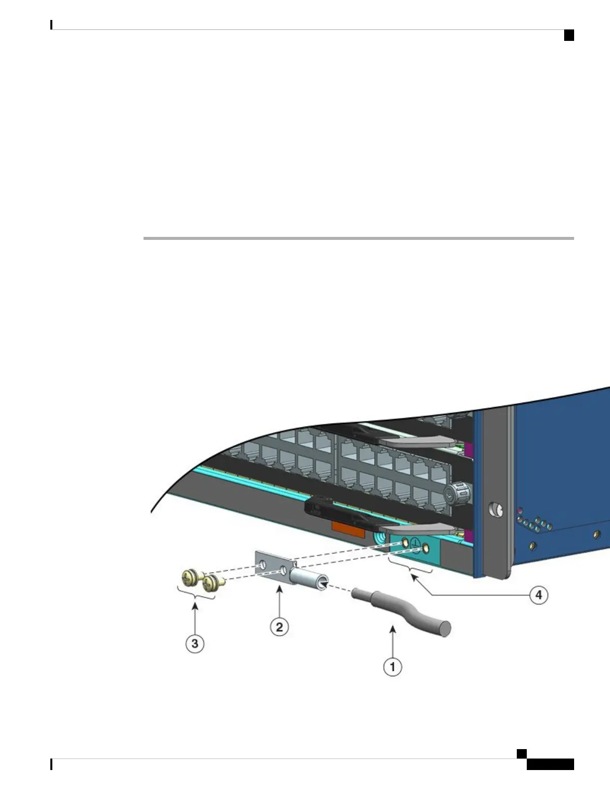
Step 2 Insert the stripped end of the grounding wire into the open end of the grounding lug.
Step 3 Crimp the grounding wire in the barrel of the grounding lug. Verify that the ground wire is securely attached
to the ground lug.
Step 4 Secure the grounding lug to the system ground connector with two M4 screws. Ensure that the grounding lug
and the grounding wire do not interfere with other switch hardware or rack equipment.
Figure 24: Locating and Connecting System Ground
Cisco Catalyst 9400 Series Switches Hardware Installation Guide
75
Installing the Switch
Establishing System Ground
 Loading...