19
®
GENERAL
- WATER /AERAULIC CONNECTIONS -
Install ON/OFF valves next to the parts that are subject to maintenance. This allows their replacement without having to empty the
system.
The pipework must be designed with the minimum possible difference in height. Install automatic or manual vents in the high points of
the piping to allow the outlet of the air in the circuit. The system can be kept at the right pressure by means of an expansion vessel or
of a combined pressure reduction-discharge valve.
All the water pipes must be insulated in order to prevent condensation and heat dispersions along the piping itself. Make sure that the
insulation is vapour seal type.
Check for any leaks in the piping before insulating it. Air-venting and draining connections must protrude outside of the insulation so
as to be accessible.
The weight of the water connections must be adequately supported by the outside of the unit. The fittings on the exchanger must not
be subject to stress.
For units with antivibration mounts, flexible joints must be used for the water connections.
It is suggested to install thermometers, pressure gauges and bleed valves at the inlet/outlet of the unit, as this will help in the routine
checking and maintenance of the unit.
ATTENTION:
The installation of a steel mesh strainer on the inlet of the exchangers must be scheduled in order to protect them from foreign
materials.
Danger of frost.
If the unit and its water connections are subject to temperatures lower than 0°C, specific actions must be taken to avoid frost on the
exchanger and in the corresponding water circuit.
If the unit is fitted with an antifreeze heater (standard oR optional, depending on the model) on the exchanger side, this must always
be powered together with the heaters in the water circuit.
An antifreeze solution can be used (e.g. Ethylene Glycol) in the required percentage (see the Technical bulletin).
The water circuit (including the exchanger) can be drained during for seasonal shut-down.
Carefully check that there are no leaks from the pipes when filling the system.
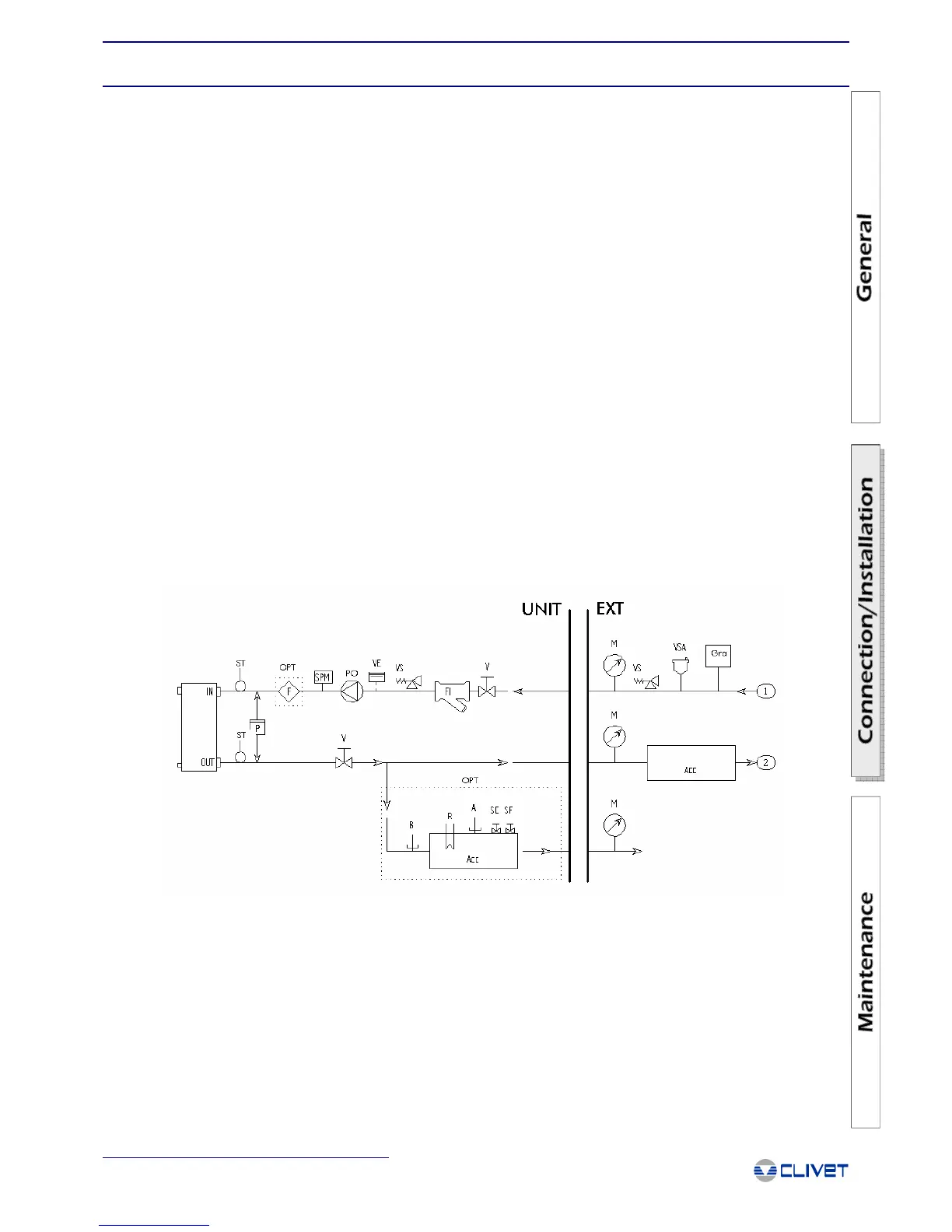
Water/Aeraulic Connections
If the flow switch is not installed on the unit, it must be fitted in the system.
For units operating in parallel with on-board hydronic assemblies, a non-return valve should be fitted, to prevent the circulation of
water.
UNIT = unit
EXT = exterior
VS = water side safety valve
SPM = water side minimum pressure switch
SF = air vent stop valve
SC = discharge stop valve
P = differential pressure switch
B = water side low temperature switch
VE = expansion tank
V = cock
VSA = automatic air vent
ST = water inlet and outlet probes
F = optional flow switch
PO = pump
A = water side high temperature switch
R = resistor
FI = water side filter
M = manometer
ACC = storage
GRA = filling valve
OPT = optional
SUGGESTED WATER CONNECTION DIAGRAM

 Loading...