2
®
F1 = Cooling capacity correction factors
FK1 = Compressors' input power correction factors
GENERAL WARNINGS
This manual has been designed to enable the unit to be installed, started up and maintained correctly, making it essential to observe
the following points:
- these instructions should be read carefully;
- the unit must be installed, tested and maintained by expert personal who meet the relevant legal requirements (Italian law No. 46 of
5/3/1990).
- The manufacturer declines all liability for any electrical and/or mechanical changes to the unit, which also invalid its guarantee. Any
operations whatsoever that have not been expressly authorised and do not respect the information in this manual shall invalidate the
guarantee.
- Observe the local safety regulations in force when installing the unit.
- Make sure the power supply conforms to the data on the unit’s rating plate, located inside the door of the main electrical panel.
- This manual and the unit’s wiring diagram should be carefully stored so that they are readily available to the operator when required.
- The packaging material (plastic bags, polystyrene foam, nails, etc.) is potentially dangerous and should therefore be kept away from
children and recycled in compliance with the local regulations in force.
- The unit must only be used for the specific purpose it was designed, as described in the paragraph GENERAL TECHNICAL
SPECIFICATIONS Any use other than that specified does not imply any commitment or constraint by the manufacturer in any way
whatsoever.
- Switch off the unit in the event of faults or poor operation.
- Only have repairs carried out by a service centre authorised by the manufacturer, and insist on the use of original spare parts only.
Failure to comply with the above may compromise the safety of the unit.
The manufacturer declines all liability for any damage that may be caused whether directly or indirectly to persons or things if these
instructions are not heeded.
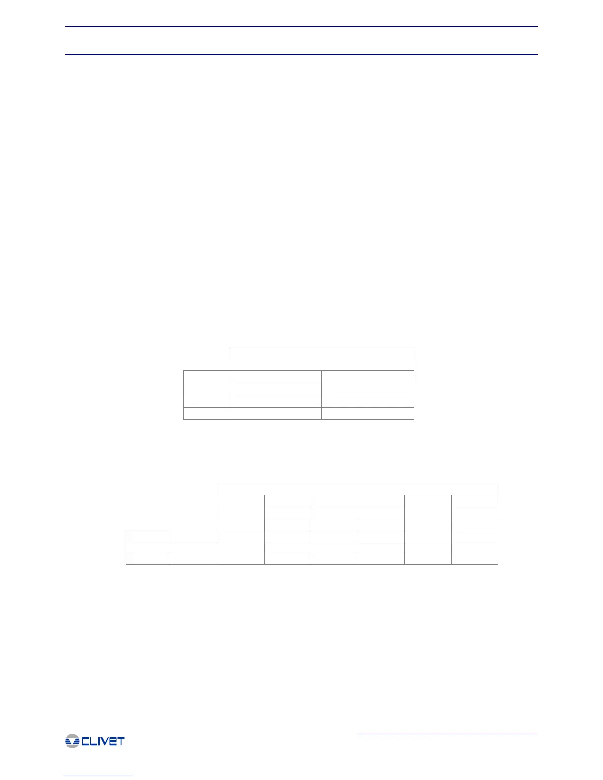
CORRECTION FACTORS
The performance data described in the general technical specifications is based on an evaporator fouling factor of 0.44x10⁻⁴ m2 x°C/
W and perfectly clean finned coils. For different value fouling factors, the performance data must be multiplied by the following
correction coefficients.
OPERATION LIMITS AND USE OF THE EXCHANGERS
- GENERAL INFORMATION-
General Information
CORRECTION FACTORS
m
2
°C / W
F1 FK1
0.44 x 10⁻⁴
1 1
0.88 x 10⁻⁴
0.97 0.99
1.76 x 10⁻⁴
0.94 0.98
Evaporator
Evaporator
DPr DPw Dteo Dtei
[kPa] [kPa] [°C]
S-B S B (*)
CLIVET C
3450 2500 6 -8 22
PED CE
3450 3450 6 -8 22
UDT U
- - 6 -8 22
[°C]
DT
[°C]
5
5
5
DPr = Maximum operating pressure at refrigerant side
DPw = Maximum operating pressure at water side
DTeo = Minimum water temperature at evaporator outlet
DTei = Maximum water temperature at evaporator inlet
DT = inlet / outlet temperature differential
S = Standard
B = Brine
(*) = Limit for 2 capacity steps unit

 Loading...