5
®
OPERATING LIMITS
The water flow-rate at the evaporator must be constant and fall within MIN-MAX limits shown in the diagram/diagrams under the
section on "Water/Aeraulic Connections".
Version S / Configuration ST
General Information
Version S / Configuration LN
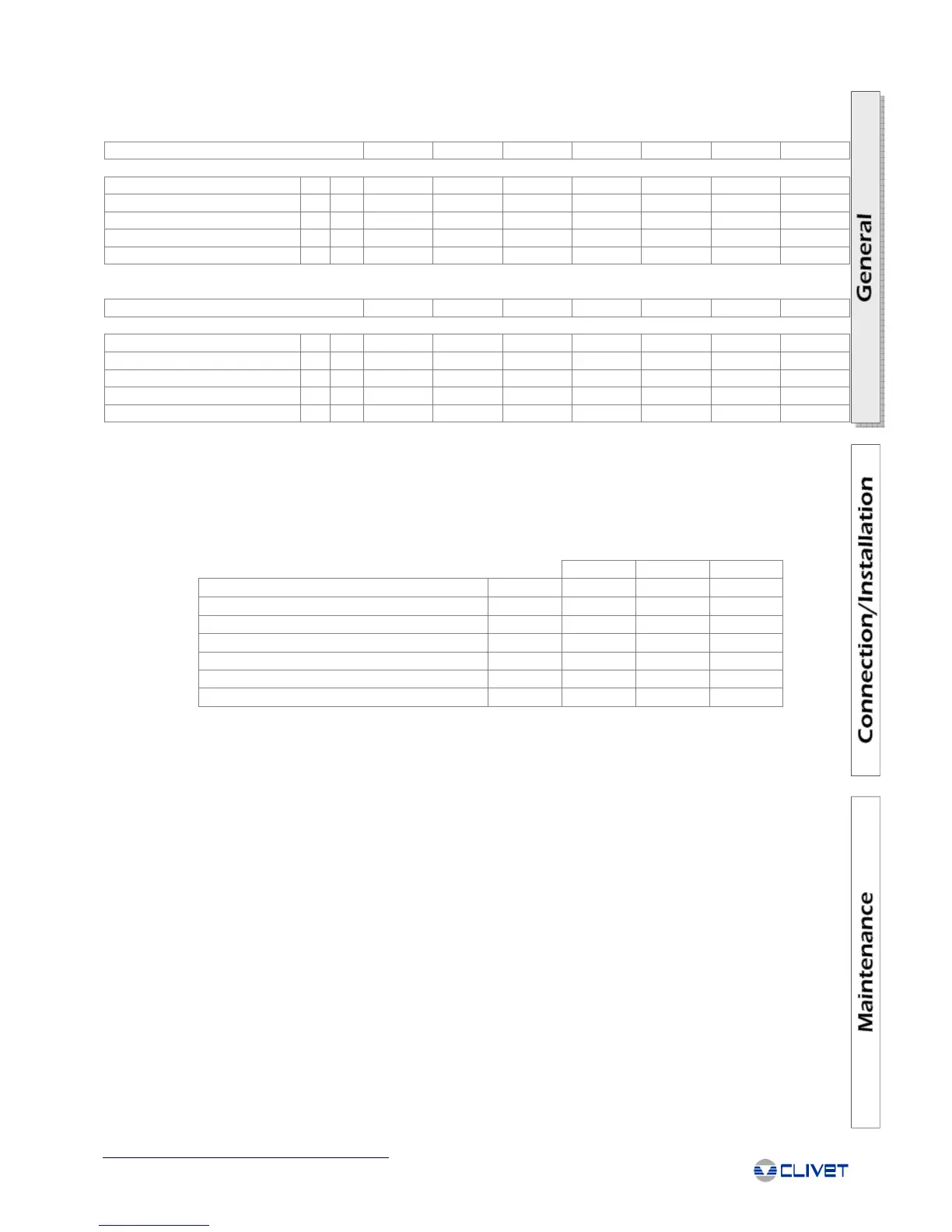
SETTING THE CUT-OUT DEVICES AND CONTROLS
Opens Closes Value
High pressure switch [kPa] 2800 2000 -
Low pressure switch [kPa] 230 360 -
Antifreeze protection [°C] 4 6.5 -
High pressure safety valve [kPa] - - 3000
Low pressure safety valve [kPa] - - 1900
Max compressor starts per hour [n°] - - 10
Safety discharge thermostat [°C] - - 120
SIZE
302 323 404 464 524 564 614
Condenser
Max. air inlet temperature (1) [°C] 47.5 47.5 47.5 47 48.5 47 46
Max. air inlet temperature (2) [°C] 53.5 53.5 52.5 52 53 52.5 52
Min. air inlet temperature (3) [°C] -10 -10 -10 -10 -10 -10 -10
Min. air inlet temperature (4) [°C] 6 11 11 10 8 7 5
Min. air inlet temperature (5) [°C] 16 19.5 19.5 19 18 17.5 14.5
SIZE
302 323 404 464 524 564 614
Condenser
Max. air inlet temperature (1) [°C] 44.5 44.5 44.5 44.5 45.5 44 43
Max. air inlet temperature (2) [°C] 50 50 50 50 51 49.5 49
Min. air inlet temperature (3) [°C] -10 -10 -10 -10 -10 -10 -10
Min. air inlet temperature (4) [°C] 6 11 11 10 8 7 5
Min. air inlet temperature (5) [°C] 16 19.5 19.5 19 18 17.5 14.5
1) Unit at full load - Evaporator water = 12/7°C
2) Unit at partial load (automatic partialization)
3) With electronic low ambient temperature control (std), unit at full load and motionless external air
4) With electronic low ambient temperature control (std), unit at partial load and motionless external air
5) With electronic low ambient temperature control (std), unit at partial load with air speed 1m/s
Note: The electronic low ambient temperature control with inverter is recommended for temperatures lower than 5°C

 Loading...