40
®
Control
Out_D_1:
1. Relay energised
2. Relay de-energised
3. Not used
4. Reverse cycle valve circuit 2 (DO-4)
5. Compressor 2 (DO-3)
6. Reverse cycle valve circuit 1 (DO-2)
7. Compressor 1 (DO-1)
8. Compressor 4 (DO-8)
9. Compressor 3 (DO-7)
10. Antifreeze heater (DO-6)
1. Status menu
2. Date and time
3. Current set point
4. Outside Temperature Compensation Value
5. Water Reset Compensation Value
6. Load Compensation Value
7. Exchanger inlet temperature
8. Exchanger 1 outlet temperature
9. Exchanger 2 outlet temperature
10. Condensing temperature circuit 1
11. Condensing temperature circuit 2
12. Condensing pressure circuit 1
13. Condensing pressure circuit 2
14. Demand Limit signal value
15. Water Reset signal value
16. Outside air temperature
17. Outside air relative humidity
18. Outside air specific humidity
19. Status of compressor 1
20. Status of compressor 2
21. Status of compressor 3
22. Status of compressor 4
23. Circuit 1 Defrost
24. Circuit 2 Defrost
25. Fan output % value Circuit 1
26. Fan output % value Circuit 2
27. Status of digital inputs 1 (see par. "Digital inputs")
28. Status of digital inputs 2 (see par. "Digital inputs")
29. Status of digital outputs 1 (see par. "Digital outputs")
30. Status of digital outputs 2 (see par. "Digital outputs")
31. Status of plug in digital outputs (see par. "Digital outputs")
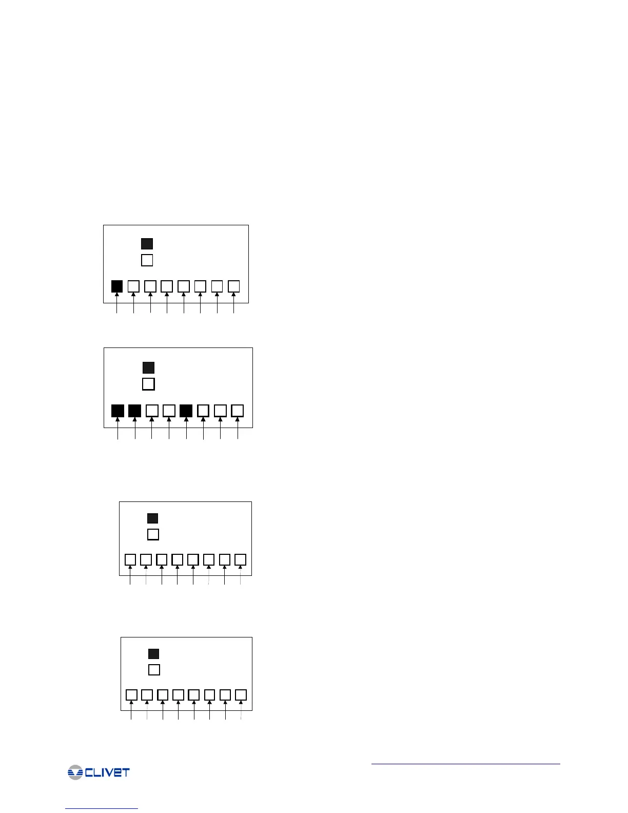
DIGITAL INPUTS
Correspondence between position and digital input in the status indication row IN_DI_1
(3)
In Di 1
(1)
(2)
(4) (5) (6) (7) (8) (9) (10)
In Di 1:
1. Contact closed
2. Contact open
3. Flow switch (DI-12)
4. Alarm compressor 3 (DI-11)
5. Fan overload circuit 2 (DI-10)
6. Overload compressor 2 (DI-9)
7. Low pressure circuit 2 (DI-8)
8. High pressure circuit 2 (DI-7)
9. Fan overload circuit 1 (DI-6)
10. Overload compressor 1 (DI-5)
Correspondence between position and digital input in the status indication row IN_DI_2
Correspondence between the position and the digital output in the status indication row OUT_D_1
In Di 2
(1)
(2)
(3) (4) (5) (6) (7) (8) (9) (10)
In Di 2:
1. Contact closed
2. Contact open
3. Water fill system (DI-16)
4. Second set point (DI-15)
5. Overload compressor 4 (DI-14)
6. Phase monitor (DI-13)
7. Remote ON-OFF (DI-1)
8. Remote HEAT-COOL (DI-2)
9. High pressure circuit 1 (DI-3)
10. Low pressure circuit 1 (DI-4)
DIGITAL OUTPUTS
Out_D_1
(1)
(2)
(3)
(5)
(6)
(7) (8)
(9)
(10)
(4)
Out_D_2:
1. Relay energised
2. Relay de-energised
3. Pump 1 (DO-5)
4. Status of compressor 1 (DO-10)
5. Status of compressor 2 (DO-9)
6. Cumulative fault alarm (DO-11)
7. Not used
Correspondence between the position and the digital output in the status indication row OUT_D_2
Out_D_2
(1)
(2)
(3)
(5)
(6)
(7) (7)
(7)
(7)
(4)

 Loading...