InteliLite
NT
– AMF20/25, SW version 2.2, ©ComAp – September 2014 47
IL-NT-AMF-2.2-Reference Guide.pdf
Recommended CAN/RS485 connection
CAN bus connection
The bus has to be terminated by 120 Ohm resistors at both ends.
External units can be connected on the CAN bus line in any order, but keeping line arrangement (no
tails, no star) is necessary.
Standard maximum bus length is 200m
Shielded cable has to be used, shielding has to be connected to PE on one side (controller side).
A) For shorter distances (all network components within one room) – picture 1
Interconnect H and L; shielding connect to PE on controller side
B) For longer distances (connection between rooms within one building) – picture 2
Interconnect H, L, COM; shielding connect to PE in one point
C) In case of surge hazard (connection out of building in case of storm etc.) – picture 3
We recommend to use following protections:
- Phoenix Contact (http://www.phoenixcontact.com):
PT 5-HF-12DC-ST with PT2x2-BE (base element)
- Saltek (http://www.saltek.cz):
DM-012/2 R DJ
Recommended data cables: BELDEN (http://www.belden.com)
A) For shorter distances: 3105A Paired - EIA Industrial RS-485 PLTC/CM (1x2 conductors)
B) For longer distances: 3106A Paired - EIA Industrial RS-485 PLTC/CM (1x2+1 conductors)
C) In case of surge hazard: 3106A Paired - EIA Industrial RS-485 PLTC/CM (1x2+1 conductors)
RS485 connection
The line has to be terminated by 120 Ohm resistors at both ends.
External units can be connected on the RS485 line in any order, but keeping line arrangement (no
tails, no star) is necessary.
Standard maximum link length is 1000m.
Shielded cable has to be used, shielding has to be connected to PE on one side (controller side).
A) For shorter distances (all network components within one room) – picture 1
interconnect A and B; shielding connect to PE on controller side
B) For longer distances (connection between rooms within one building) – picture 2
interconnect A, B, COM; shielding connect to PE in one point
C) In case of surge hazard (connection out of building in case of storm etc.) – picture 3
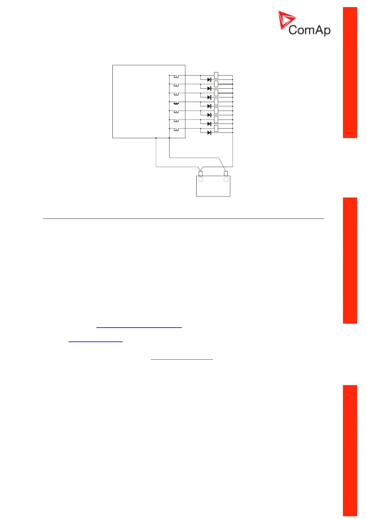
+
Battery
-
iL
LOAD
+
-
Power
Supply
 Loading...