InteliLite
NT
– AMF20/25, SW version 2.2, ©ComAp – September 2014 98
IL-NT-AMF-2.2-Reference Guide.pdf
Sensor Specification
Background of the sensor calibration
To correct measuring error of each analog input (pressure, temperature, level) calibrating constants
within 10 % of measure range should be set. Two calibrating constants are set in physical units - bar,
o
C, % .Calibration is made by adding the value of setpoint AIxCalibration directly to the calculated
value at analog input.
Hint:
The calibration must be done at the operational point of the analog input (e.g. 80°C, 4.0Bar etc..)
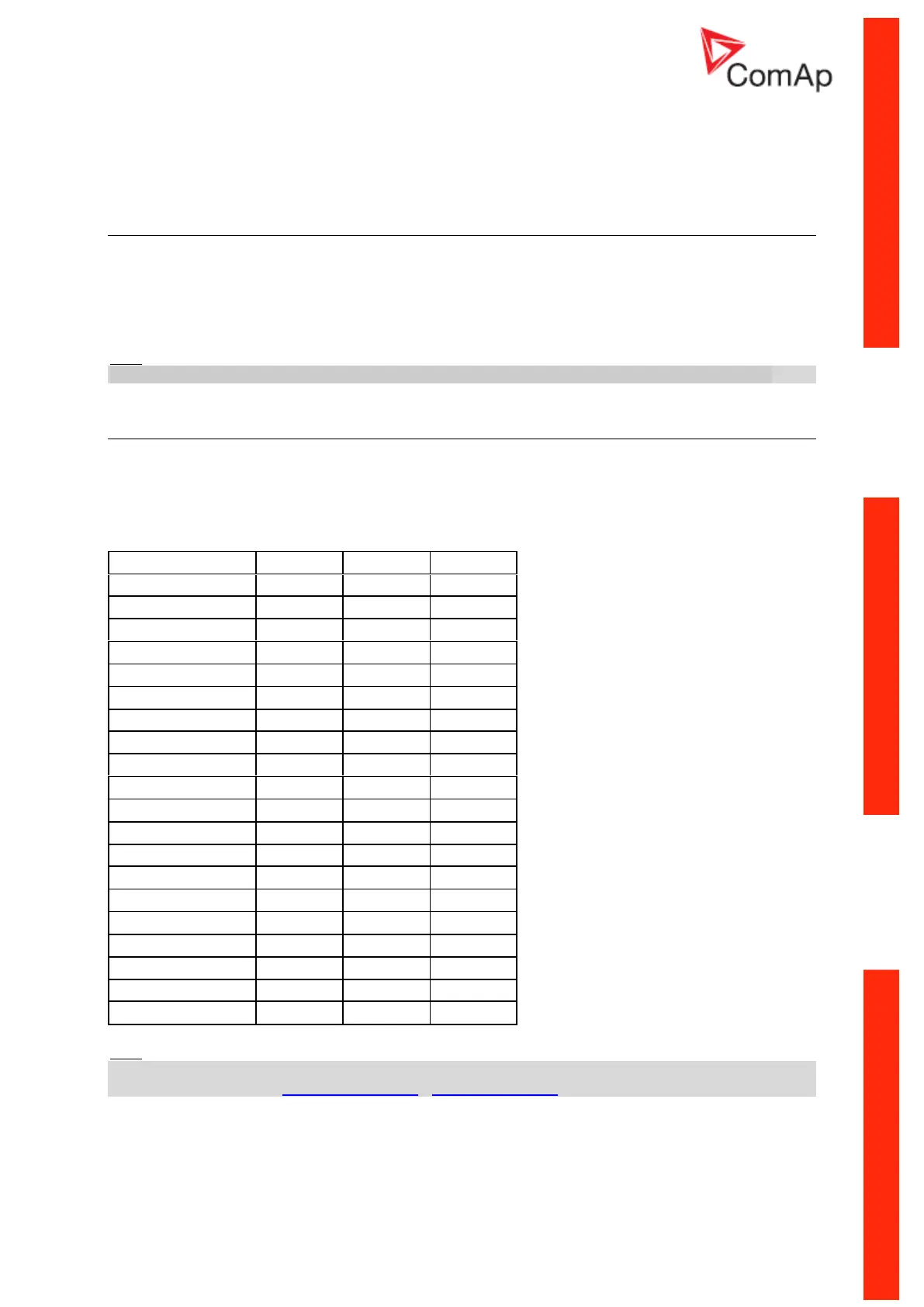
Default sensor curves
There are 20 default resistive curves available. The following table provides information on
minimum/maximum values of respective sensors. Actual values especially of temperature curves may
differ. Meaning is to prolong curve to the lower temperature values, so the cold engine will not raise
alarm fail sensor.
Hint:
You can find detail information on sensors in LiteEdit Reference Guide and details about sensor fails
in this manual in chapter Alarm Management - Sensor Fail (FLS).
 Loading...