assembly and alignment
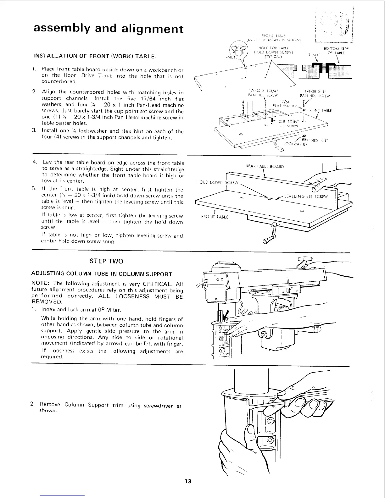
INSTALLATION OF FRONT (WORK) TABLE.
1.
Place front table board upside down on a workbench or
on the floor. Drive T-nut into the hole that is not
counterbored.
2. Align the counterbored holes with matching holes in
support channels. Install the five 17/64 inch flat
washers, and four ¼- 20 x 1 inch Pan-Head machine
screws. Just barely start the cup point set screw and the
one (1) V4- 20x 1-3/4 inch Pan Head machine screw in
table center holes.
3. Install one ¼ Iockwasher and Hex Nut on each of the
four (4) screws in the support channels and tighten. HEX NUT
LOCKWASHER
"._
4.
5.
Lay the rear table board on edge across the front table
to serve as a straightedge. Sight under this straightedge
to determine whether the front table board is high or
low at its center.
If the front table is high at center, first tighten the
center ("A -- 20 x 1-3/4 inch) hold down screw until the
table is evel - then tighten the leveling screw until this
screw is mug.
If table is low at center, first tighten the leveling screw
until th,t table is level then tighten the hold down
screw•
If table is not high or tow, tighten leveling screw and
center hold down screw snug.
HOLD DOWN SCREW
f
FRONT TABLE
REAR TABLE BOARD
STEP TWO
ADJUSTING COLUMN TUBE IN COLUMN SUPPORT
NOTE: The following adjustment is very CRITICAL. All
future alignment procedures rely on this adjustment being
performed correctly. ALL LOOSENESS MUST BE
REMOVED.
1. Index and lock arm at 0° Miter.
While holding the arm with one hand, hold fingers of
other hand as shown, between column tube and column
support. Apply gentle side pressure to the arm in
opposing directions. Any side to side or rotational
movement (indicated by arrow) can be felt with finger.
If looseness exists the following adjustments are
required.
2. Remove
shown.
Column Support trim using screwdriver as
i
13
 Loading...