assembly and alignment
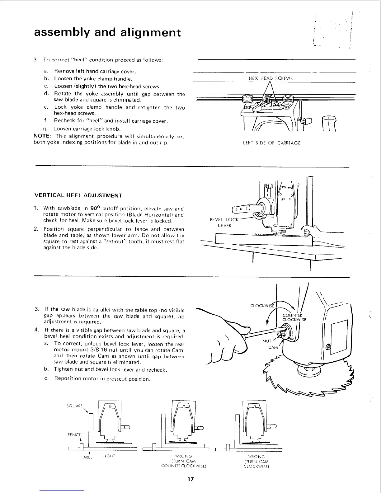
3. To correct "heel" condition proceed as follows:
a. Remove left hand carriage cover.
b, Loosen the yoke clamp handle.
c. Loosen (slightly) the two hex-head screws.
d. Rotate the yoke assembly until gap between the
saw blade and square is eliminated,
e. Lock yoke clamp handle and retighten the two
hex-head screws.
f, Recheck for "heel" and install carriage cover.
g. Loosen carriage lock knob.
NOTE: This alignment procedure will simultaneously set
both yoke =ndexing positions for blade in and out rip.
: J
• '. f_
! "" i
HEX HEAD SCREWS
LEFT SIDE OF CARRIAGE
VERTICAL HEEL ADJUSTMENT
1. With sawblade in 90 ° cutoff position, elevate saw and
rotate motor to vertical position (Blade Horizontal) and
check for heel. Make sure bevel lock lever is locked.
2. Position square perpendicular to fence and between
blade and table, as shown lower arm. Do not allow the
square to rest against a "set-out" tooth, it must rest flat
against the blade side.
3.
4,
If the saw blade is parallel with the table top (no visible
gap appears between the saw blade and square), no
adjustment is required.
If there is a visible gap between saw blade and square, a
bevel heel condition exists and adjustment is required.
a. To correct, unlock bevel lock lever, loosen the rear
motor mount 3/8-16 nut until you can rotate Cam,
and then rotate Cam as shown until gap between
saw blade and square is eliminated.
b. Tighten nut and bevel lock lever and recheck.
c. Reposition motor in crosscut position.
\
I
COUNTER
SQUA k
FENCE_! !
TABLE RIGHT WRONG
(TURN CAM
COUNTERCLOCKWISE)
WRONG
(TURN CAM
CLOCKWISE)
17
 Loading...