2.
3.
4.
5.
Since the work is pushed along the fence, it must have a
straight edge n order to make sliding contact with the
fence. Also, the work must make solid contact with the
table, so that it will not wobble. Provide a straight edge,
even t this means temporarily nailing of an auxiliary
straight-edged board to the work. If the workpiece is
warped, turn the hollow side down.
Alwa_ s use the saw guard and make sure the spreader is
correctly aligned with the saw kerf and antikickback
pawls properly adjusted. Wood cut with the grain tends
to spring the kerf closed and bind the blade and a
kickb_lck could occur.
Stand a little to one side of center to be clear of,work
in cas_, of kickback.
When tipping short or narrow work, always use a push
stick applied to the section of the workpiece between
the blade and fence . . . push the work past the blade so
it is clear of the blade. This procedure will minimize the
possibility of kickbacks.
In-Ripping. The radial arm and bevel are indexed at 0 ° and
locked, but the yoke is turned 90-degrees in a clockwise
direction I viewed from above) from the crosscut position.
Thus, wh_m standing in front of the saw, the blade would
be rotating counterclockwise. After positioning the guard
and antikickback mechanism the workpiece is fed from the
right-hanoi side of the saw. The "Blade In-Rip" scale is on
the right-hand side of radial arm.
Out-Ripping. The radial arm and bevel are indexed at 0 °
and locked, but the yoke is turned 90-degrees in a
counterclockwise direction (viewed from above), from the
crosscut position. When standing in front of the saw, blade
would be rotating clockwise. After positioning the guard
and antikickback mechanism the workpiece is fed from the
left-hand side of the saw. The"Blade Out-Rip" scale is on
the left hand side of radial arm.
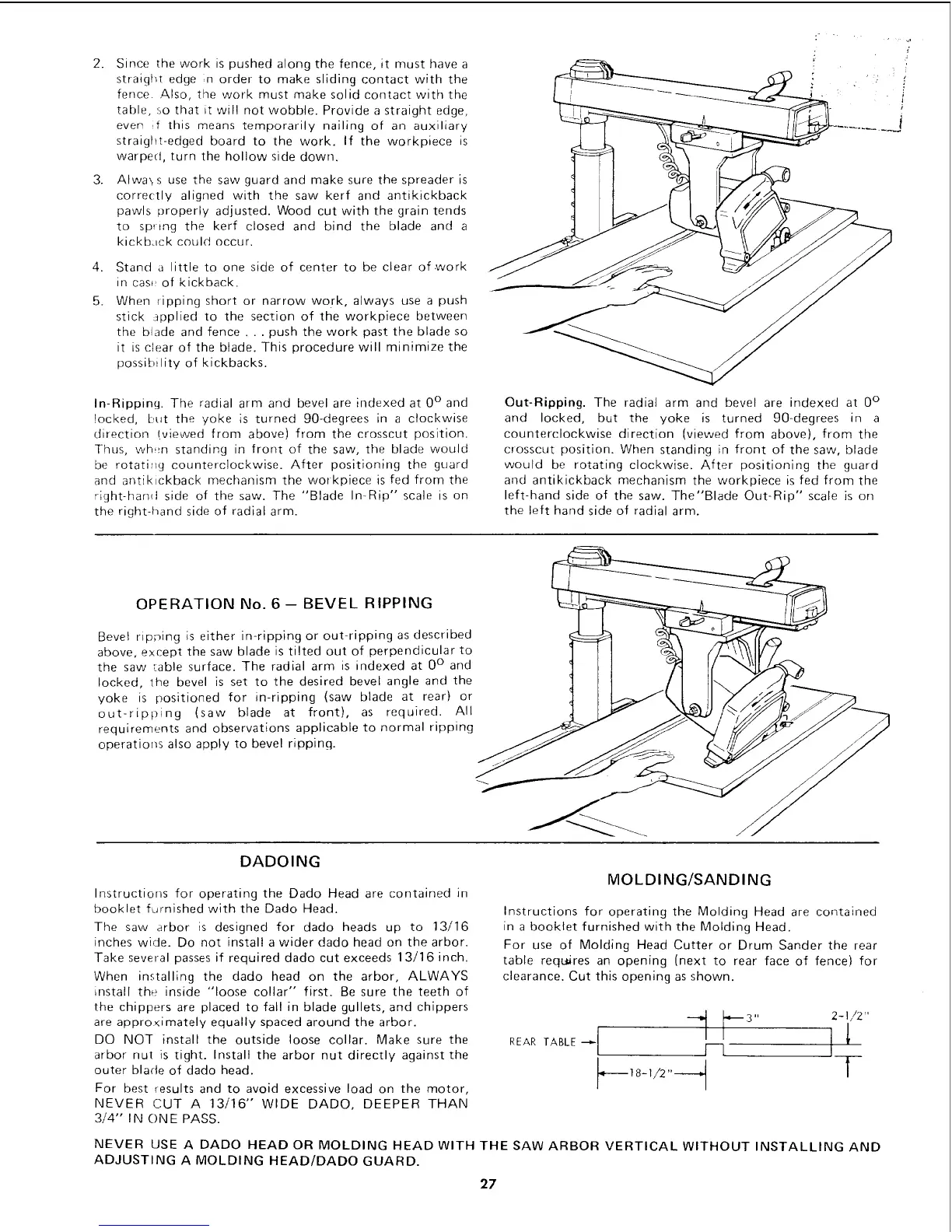
OPERATION No. 6 -- BEVEL RIPPING
Bevel ripping is either in-ripping or out-ripping as described
above, except the saw blade is tilted out of perpendicular to
the saw _able surface. The radial arm is indexed at 0 ° and
locked, the bevel is set to the desired bevel angle and the
yoke is positioned for in-ripping (saw blade at rear) or
out-ripping (saw blade at front), as required. All
requirements and observations applicable to normal ripping
operations also apply to bevel ripping.
DADOING
Instructions for operating the Dado Head are contained in
booklet furnished with the Dado Head.
The saw arbor is designed for dado heads up to 13/16
inches wide. Do not install a wider dado head on the arbor.
Take several passes if required dado cut exceeds 13/16 inch.
When installing the dado head on the arbor, ALWAYS
ins[all the inside "loose collar" first. Be sure the teeth of
the chippers are placed to fall in blade gullets, and chippers
are appro<imately equally spaced around the arbor.
DO NOT install the outside loose collar. Make sure the
arbor nut is tight. Install the arbor nut directly against the
outer blade of dado head.
For best results and to avoid excessive load on the motor,
NEVER CUT A 13/16" WIDE DADO, DEEPER THAN
3/4" IN ONE PASS.
MOLDING/SANDING
Instructions for operating the Molding Head are contained
in a booklet furnished with the Molding Head.
For use of Molding Head Cutter or Drum Sander the rear
table req_res an opening (next to rear face of fence) for
clearance. Cut this opening as shown.
_
REAR TABLE _
NEVER USE A DADO HEAD OR MOLDING HEADWITH THE SAW ARBOR VERTICAL WITHOUT INSTALLING AND
ADJUSTING A MOLDING HEAD/DADO GUARD.
27
 Loading...