5 Electrical installation
Installation manual
15
EGSAH/X06+10UDA9W
Daikin Altherma 3 GEO
4P598591-1A – 2019.12
5.2 Overview of electrical connections
for external and internal actuators
Item Description
Power supply See "5.3To connect the main power
supply"[415].
Remote outdoor
sensor
See "5.4To connect the remote outdoor
sensor"[418].
Shut-off valve See "5.5To connect the shut-off valve
(Heating/Cooling)"[418].
Electricity meter See "5.6To connect the electricity
meters"[419].
Domestic hot water
pump
See "5.7To connect the domestic hot water
pump"[419].
Alarm output See "5.8To connect the alarm
output"[420].
Space cooling/heating
operation control
See "5.9To connect the space cooling/
heating ON/OFF output"[421].
Changeover to
external heat source
control
See "5.10To connect the changeover to
external heat source"[422].
Power consumption
digital inputs
See "5.11To connect the power
consumption digital inputs"[422].
Safety thermostat See "5.12To connect the safety thermostat
(normally closed contact)"[423].
Brine low pressure
switch
See "5.13To connect the brine low
pressure switch"[423].
Thermostat for passive
cooling
See "5.14To connect the thermostat for
passive cooling"[424].
LAN adapter
connections
See "5.15LAN adapter"[424].
Room thermostat
(wired or wireless)
See:
▪ Installation manual of the room
thermostat (wired or wireless)
▪ Addendum book for optional
equipment
Wires for wired room thermostat: (3
for cooling/heating operation; 2 for
heating only operation)×0.75mm²
Wires for wireless room thermostat: (5
for cooling/heating operation; 4 for
heating only operation)×0.75mm²
Maximum running current: 100mA
For the main zone:
▪ [2.9] Control
▪ [2.A] Thermostat type
For the additional zone:
▪ [3.A] Thermostat type
▪ [3.9] (read-only) Control
Item Description
Heat pump convector See:
▪ Installation manual of the heat
pump convectors
▪ Addendum book for optional
equipment
Wires: 4×0.75mm²
Maximum running current: 100mA
For the main zone:
▪ [2.9] Control
▪ [2.A] Thermostat type
For the additional zone:
▪ [3.A] Thermostat type
▪ [3.9] (read-only) Control
Remote indoor sensor See:
▪ Installation manual of the remote
indoor sensor
▪ Addendum book for optional
equipment
Wires: 2×0.75mm²
[9.B.1]=2 (External sensor = Room)
[1.7] Room sensor offset
Current sensors See the installation manual of the
current sensors.
Wires: 3×2. Use part of the cable
(40m) delivered as accessory.
[9.9.1]=3 (Power consumption
control = Current sensor)
[9.9.E] Current sensor offset
Human Comfort
Interface
See:
▪ Installation and operation manual of
the Human Comfort Interface
▪ Addendum book for optional
equipment
Wires: 2×(0.75~1.25mm²)
Maximum length: 500m
[2.9] Control
[1.6] Room sensor offset
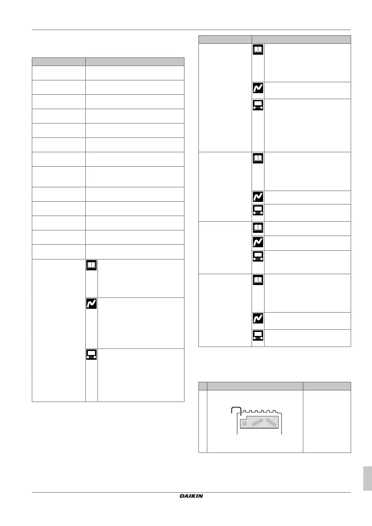
5.3 To connect the main power supply
Use one of the following layouts to connect the power supply (for
details of C1~C5, see below the table):
# Layout Open the unit
(a)
1 Single cable power supply (=combined
power supply)
C1: Power supply for the backup heater,
and the rest of the unit (1N~ or 3N~)
Not necessary
(connection to
factory-mounted
cable outside of the
unit)

 Loading...